Garmin GNC 420AW Pilot'S Manual & Reference Download Page 164

9 - AUX PAGES

154

190-00356-00 Rev B

Flight Planning

4.   Turn the 

large right 

knob to hghlght the 

departure tme (DEP TIME) field. 

5.   Use the 

small

 and 

large


right 

knobs to enter 

the departure tme. Press 

ENT

 when finshed. 

(Departure tme may be entered n local or UTC 
tme, dependng upon unt settngs.) 

6.   The flashng cursor moves to the ground speed 

(GS)  field.  Use  the 

small

  and 

large


right 

knobs to enter the ground speed. Press 

ENT


when finshed. 

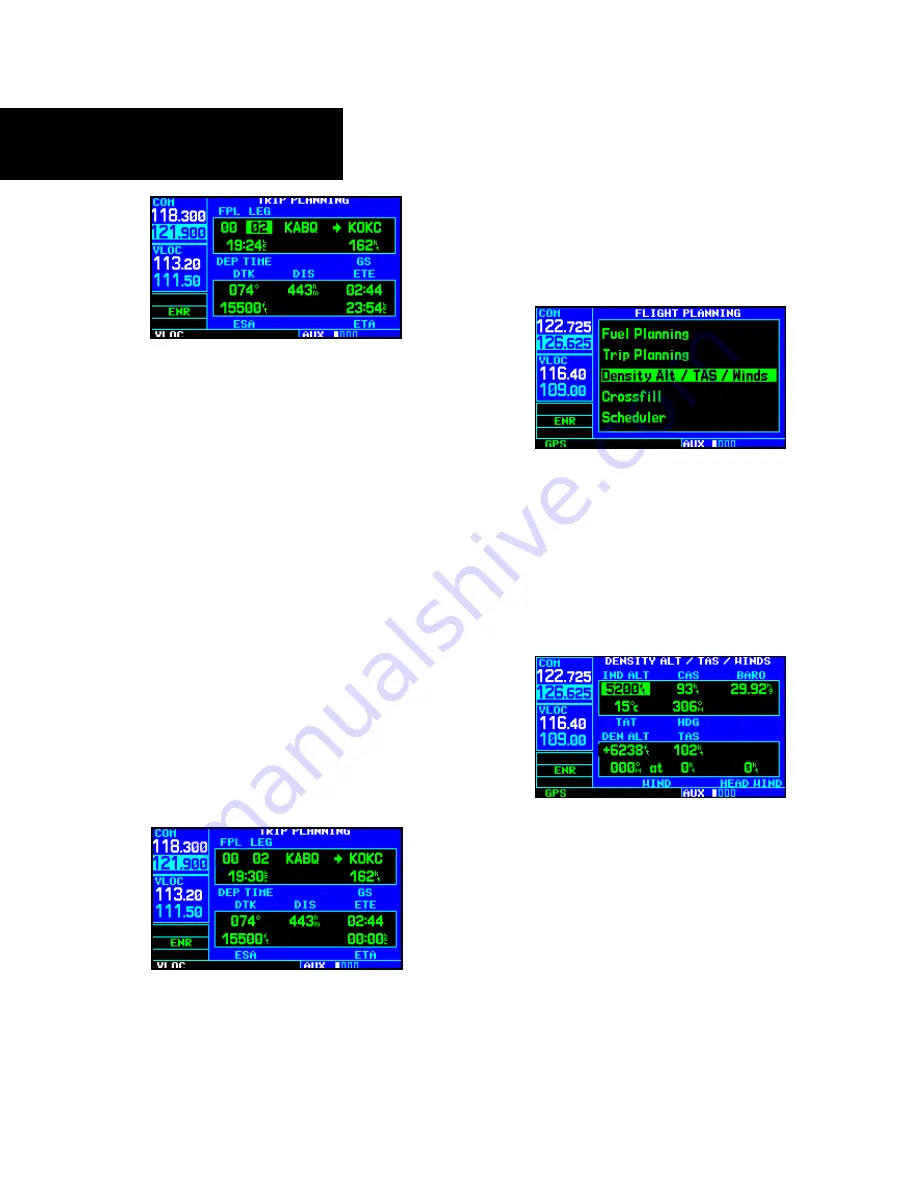
7.   Wth all varables entered, the followng nfor-

maton wll be provded: 

• DTK—    Desired track, or desired course

• DIS—   Distance

• ETE—    Estimated time en route

• ESA—    En route safe altitude

• ETA—    Estimated time of arrival

Density Alt / TAS / Winds

To calculate density altitude, true airspeed, winds 
aloft: 

1.   Select “Densty Alt / TAS / Wnds” from the 

flght plannng page. 

2.   The flashng cursor hghlghts the ndcated alt-

tude (IND ALT) field. Use the 

small

 and 

large


right 

knobs to enter the alttude ndcated on 

your altmeter. Press 

ENT

 when finshed. 

3.   The flashng cursor moves to the calbrated 

arspeed (CAS) field. Use the 

small

 and 

large


right 

knobs to enter the arspeed from your 

arspeed ndcator. Press 

ENT

 when finshed. 

4.   The flashng cursor moves to the barometrc 

settng (BARO) field. Use the 

small

 and 

large


right 

knobs to enter the barometrc settng 

(altmeter settng). Press 

ENT

 when finshed. 

5.   The flashng cursor moves to the total ar tem-

perature (TAT) field. Use the 

small

 and 

large


right 

knobs to enter the temperature. Press 

ENT

 when finshed. 

Summary of Contents for GNC 420AW

Page 1: ...Pilot s Guide Reference 400W Series ...

Page 2: ...Except as expressly provided herein no part of this manual may be reproduced copied transmitted disseminated downloaded or stored in any storage medium for any purpose without the express written permission of Garmin Garmin hereby grants permission to down load a single copy of this manual and of any revision to this manual onto a hard drive or other electronic storage medium to be viewed for pers...

Page 3: ... receiver to receive and decode the satellite signals In such event the interference may be reduced or eliminated by switching off the source of interference or moving the GPS receiver away from it CAUTION The electronic chart is an aid to naviga tion and is designed to facilitate the use of authorized government charts not replace them Land and water data is provided only as a general reference t...

Page 4: ...t any interference received including interference that may cause undesired operation To obtain accessories for your 400W series please contact your Garmin dealer Help us better support you by completing our on line registra tion form today Registration ensures that you will be notified of product updates and new products and provides lost or sto len unit tracking Please have the serial number of ...

Page 5: ...a Installation Rack Connectors Pilot s Guide Quick Reference 400W 500W Series Display Interfaces Addendum 400W 500W Series Garmin Optional Display Interfaces Addendum GNS 400W 500W series Simulator Training CD ROM Database Subscription Packet Warranty Registration Card Upgrade Package Garmin 400W series Unit NavData Card Terrain Card optional GPS Antenna Pilot s Guide Reference Quick Reference 400...

Page 6: ...HANTABILITY OR FITNESS FOR A PARTICULAR PURPOSE STATUTORY OR OTHERWISE THIS WARRANTY GIVES YOU SPECIFIC LEGAL RIGHTS WHICH MAY VARY FROM STATE TO STATE IN NO EVENT SHALL GARMIN BE LIABLE FOR ANY INCIDENTAL SPECIAL INDIRECT OR CONSE QUENTIAL DAMAGES WHETHER RESULTING FROM THE USE MISUSE OR INABILITY TO USE THIS PRODUCT OR FROM DEFECTS IN THE PRODUCT Some states do not allow the exclusion of inciden...

Page 7: ...2 Map Symbols 33 Map Range 33 Map Page Auto Zoom 34 Map Panning 35 Map Direct To 36 Airspace Information on the Map 36 Map Page Options 37 Map Setup 37 Data Fields on the Map 40 Selecting Desired On Screen Data 40 Restoring Factory Settings 41 Terrain Operation 41 Operating Criteria 41 Terrain Limitations 41 TERRAIN Alerting 42 Baro Corrected Altitude 42 Terrain Page 42 Inhibit Mode 43 Terrain Sym...

Page 8: ...er or VOR based Approaches 110 Enabling Autopilot Outputs for the King KAP140 KFC225 112 Section 6 WPT Pages 113 WPT Page Group 113 Duplicate Waypoints 115 Airport Runway Page 117 Airport Frequency Page 118 Airport Approach Page 120 Airport Arrival Page 122 Airport Departure Page 123 Intersection Page 125 NDB Page 125 VOR Page 126 User Waypoint Page 127 Creating User Waypoints 127 Creating User Wa...

Page 9: ...74 Restoring Factory Settings 174 Section 10 Fault Detection Exclusion 175 Detection and Exclusion 175 Section 11 Messages Abbreviations and Navigation Terminology 177 Messages 177 Turn Advisory and Arrival Annunciations 183 Abbreviations 184 Navigation Terms 188 Appendix A NavData Card Use 190 Appendix B Specifications 191 Appendix C Troubleshooting Q A 192 Index 198 ...

Page 10: ...INTRODUCTION viii 190 00356 00 Rev B Blank Page ...

Page 11: ... based FDE pre diction program the GPS 400W may be used for oceanic or remote operations For the latest in graphical and textual weather information the GPS 400W can connect to XM Satellite Radio s XM WX Weather Service via the GDL 69 69A datalink receiver GNC 420W 420AW The GNS 430W AW includes all of the features of the GPS 400W and also includes TSO d airborne VHF communications transceiver Thi...

Page 12: ...nd knob descriptions on the next three pages provide a general overview of the primary function s for each key and knob This Takeoff Tour section is intended to provide a brief overview of the primary functions of your 400W series unit Experi ment with the unit and refer to the Reference sections for more information Left hand Keys and Knobs Left hand Keys and Knobs GPS 400W GNC 420W AW GNS 430W A...

Page 13: ...Key and Knob Functions Right hand Keys and Knobs Right hand Keys and Knobs R The range key RNG allows you to select the desired map scale Use the up arrow side of the key to zoom out to a larger area or the down arrow side to zoom in to a smaller area D The direct to key provides access to the direct to function which allows you to enter a destination waypoint and establishes a direct course to th...

Page 14: ...nings and requirements See Sections 11 and 9 for more information on messages and unit settings The flight plan key FPL allows you to create edit activate and invert flight plans as well as access approaches departures and arrivals A closest point to flight plan feature is also available from the flight plan key See Section 4 for more information on flight plans C O F M P N GPS 400W GNC 420W GNS 4...

Page 15: ... of measure selectable fields etc the pictures shown here may not exactly match what you see on your 400W series unit Prior to using your unit for the first time we recommend that you taxi to a location that is well away from buildings and other aircraft so the unit can collect satellite data without interruption Powering up the 400W Series Unit The 420W and 430W power and COM volume are controlle...

Page 16: ...fuel capacity fuel on board and fuel flow may be manually entered if your installation does not include connection to sen sors which automatically provide these figures To enter fuel capacity fuel on board or fuel flow figures if not provided by sensors 1 Turn the large right knob to select the CAP FOB or FF field 2 Turn the small and large right knobs to enter the desired figure then press ENT En...

Page 17: ... checklists The 400W series unit can hold up to nine check lists with up to 30 entries in each checklist 2 Turn the large right knob to select the desired checklist then follow the steps in Section 9 Aux Pages Utility Page to execute each step in the selected checklist 3 Once you complete the desired checklist s press the small right knob to return to the checklists page Press the small right knob...

Page 18: ... applicable to the receiver s cur rent operating condition To return to the previous page after viewing a message press the MSG key again The satellite status page shows the ID num bers for the satellites and the relative signal strength of each satellite received as a bar graph reading Searching Sky indicates that satellite almanac data is not available The data is recollected from the first avai...

Page 19: ...the large left knob to select the desired megahertz MHz value For example the 135 portion of the frequency 135 325 3 Turn the small left knob to select the desired kilohertz kHz value For example the 325 portion of the frequency 135 325 4 To activate the selected frequency press the appropriate flip flop key COM for commu nication frequencies orVLOC forVOR Localizer frequencies Once you ve entered...

Page 20: ...The large right knob selects the page group NAV WPT AUX or NRST The small right knob selects the desired page within a group To quickly select the default NAV page press and hold the CLR key Small right knob to select pages within the group a WPT Group Arpt Location Arpt Runway Arpt Frequency Arpt Approach Arpt Arrival Intersection NDB VOR Arpt Departure User Waypoint Large right knob to change pa...

Page 21: ...ace NRST Group Large right knob to change page groups Large right knob to select pages with the group a Flight plan pages are selected by pressing the FPL key and using the small right knob to select the desired page FPL Group Active Flight Plan Flight Plan Catalog The Procedures pages are selected by pressing the PROC key and using the small or large right knobs to select a procedure PROC Group P...

Page 22: ...ctions such as flight plan ning or unit settings and listings for nearest NRST airports or other facilities To select the desired page group turn the large right knob until a page from the desired group is displayed To select the desired page within the group turn the small right knob until the desired page is displayed The bottom right corner of the screen indicates the page group currently being...

Page 23: ...k TRK and estimated time en route ETE See Sec tion 11 for definitions of these navigation terms The default NAV page is selected by pressing and holding the CLR key or turning the small right knob Active Leg of Flight Plan User selectable Data Fields Course Deviation Indicator CDI Default NAV Page To change the data fields in the corners of the Default NAV Page 1 Press MENU with the Map Page displ...

Page 24: ...mated time of arrival minimum safe altitude and ground track See Section 11 for definitions of these navigation terms Map Page Data Fields Present Position Map Display Map Scale with declutter value Desired Track The map page combines a moving map display and navigation data for complete situational awareness Map setup pages are provided to designate the maximum scale at which each map feature wil...

Page 25: ...ursor on the airport identifier field in the GPS window Turn the small right knob to display the list of airports departure arrival and en route for your flight plan or direct to Continue to turn the small right knob until the desired airport is selected 3 Press ENT to display the frequency list for the selected airport Press ENT to show the frequencies for the selected airport To select a communi...

Page 26: ...lity or city name See Section 3 for more information 2 Turn the small right knob to enter the first letter of the destination waypoint identifier The destination waypoint may be an airport VOR NDB intersection or user waypoint as long as it is in the database or stored in memory as a user waypoint 3 Turn the large right knob to the right to move the cursor to the next character position 4 Repeat s...

Page 27: ...ress ENT to display a list of available proce dures for the arrival when using approaches or STARs or departure when using SIDs airport 3 Turn the small right knob to select the desired procedure and press ENT 4 For approaches a window appears to select the desired initial approach fix IAF or provide a vectors option to select just the final course segment of the approach Turn the small right knob...

Page 28: ... eight pages avail able under the NRST group Nearest airport page Nearest intersection page Nearest NDB page Nearest VOR page Nearest user waypoints page Nearest ARTCC page Nearest FSS page Nearest airspace page To display the NRST pages 1 If necessary press the small right knob to remove the cursor from the page 2 Turn the large right knob to select the NRST page group as indicated by NRST appear...

Page 29: ...cy informa tion press the small right knob to remove the cursor and turn the small right knob to display the desired information page The nearest airport page may be used in conjunc tion with the direct to key to quickly set a course to a nearby facility in an in flight emergency Selecting a nearby airport as a direct to destination will override your flight plan or cancel a previously selected di...

Page 30: ...urned off When turned on the message MSG annunciator located directly above the MSG key will flash to alert you to the airspace message See Section 9 Aux Pages Setup 1 for information on enabling airspace alert messages To view an airspace alert message 1 Press the MSG key The message page appears with the alert message When an airspace alert occurs the message MSG annunciator will flash Press MSG...

Page 31: ...lan and activating it to use for navigation Additional information about flight plans can be found in Section 4 Flight Plans To create a new flight plan 1 Press the FPL key and turn the small right knob to select the flight plan catalog 2 Press the MENU key to display the flight plan catalog options 3 Turn the large right knob to select Create New Flight Plan and press ENT To create a new flight p...

Page 32: ...l resides in the flight plan catalog It replaces any flight plan which currently exists in flight plan 00 To activate the new flight plan 1 On the Flight Plan Catalog page press the small right knob to activate the cursor Rotate the large right knob to highlight the desired flight plan 2 Press the MENU key to display the flight plan catalog options 3 Turn the small right knob to select Activate Fl...

Page 33: ...pears at the upper right corner of the screen while transmitting Volume COM radio volume is adjusted using the COM power volume knob Turn the COM power volume knob clockwise to increase volume or counterclock wise to decrease volume Squelch The COM radio features an automatic squelch to reject many localized noise sources You may override the squelch function by pressing the COM power volume knob ...

Page 34: ...A TX indication appears at this location while you are transmitting NOTE The tuning cursor will normally appear in the COM window unless placed in the VLOC window by pressing the small left knob When the tuning cursor is in the VLOC window it will automatically return to the COM window after 30 seconds of inactivity This does not apply to the GNS 420W The active frequency in either window cannot b...

Page 35: ...key then turn the large right knob until the nearest pages appears Finally if necessary turn the small right knob to display the nearest airport page 2 Press the small right knob momentarily to place the cursor on the airport identifier field of the first airport in the list Turn the large right knob to highlight the desired airport frequency 3 Press ENT to place the frequency in the standby field...

Page 36: ...ight knob to place the cursor on the airport identifier field To the left of this field appears Departure En Route or Arrival depending on the placement of the dis played airport within your flight plan 3 Turn the small right knob to display a window listing the airports in your flight plan Continue turning the small right knob to select the desired airport 4 Press ENT to return to the NAVCOM page...

Page 37: ...s to activate the 121 500 MHz emergency frequency Note Under some circumstances if the com sys tem loses communication with the main system the radio will automatically tune to 121 500 MHz for transmit and receive regardless of the displayed frequency Stuck Microphone Whenever the 420W 430W is transmitting a TX indication will appear in the COM window If the microphone is stuck or accidentally lef...

Page 38: ...croll the entire preset frequency list through the Standby frequency box the list will wrap from the bottom of the list back up to the top skipping any empty preset positions Preset Com Frequencies are only available with SW Version 3 00 or later The standby frequency isn t activated until a Com flip flop switch either remote or bezel mounted is pressed Remote Frequency Selection only functions on...

Page 39: ...cess convenient to cycle between the default NAV and map pages two of the most frequently used pages Other pages are provided to list frequencies for your flight plan show your current position display current satellite reception and make vertical navigation settings Default NAV Map Terrain VNAV Position Satellite Status NAVCOM The bottom right corner of the screen indicates which page group is cu...

Page 40: ...eflection defined for the approach You may also manually select the desired scale set ting as outlined in the Aux Setup section The graphic CDI shows your position at the center of the indicator relative to the desired course the moving course deviation needle As with a traditional mechanical CDI when you re off course simply steer toward the needle The TO FROM arrow in the center of the scale ind...

Page 41: ...altitude MSA Track angle error TKE Ground track TRK Vertical speed required VSR Cross track error XTK If no flight plan or direct to destination has been selected only speed track altitude and minimum safe altitude data may be displayed All other data types will appear as blank lines on the default NAV page until a destination is selected To select a different data item for any data field 1 Starti...

Page 42: ...ssfill option NOTE The databases of the 400 500 series and the 400W 500W are incompatible so you may not mix systems Map Page The second NAV page is the map page which dis plays your present position using an airplane symbol along with nearby airports navaids user defined waypoints airspace boundaries lakes rivers high ways and cities NOTE The electronic chart is an aid to navigation and is design...

Page 43: ...h hard surface runway s Primary runway shown Airport with soft surface runway s only Private Airfield Intersection VOR VORTAC VOR DME TACAN DME NDB Localizer Locator Outer Marker Heliport Map Range The map display can be set to 23 different scale settings from 500 feet to 2000 nautical miles statute and metric units are also available The scale is indi cated in the lower left hand corner of the ma...

Page 44: ...moved from the map display but the airport and navaid detail will remain The Setup Map option allows you to define the maximum scale at which each map feature will appear This provides you with complete control to minimize screen clutter You can also quickly remove items from the map using the CLR key To quickly declutter the map display press the CLR key momentarily as often as needed to select t...

Page 45: ... right turn clockwise or left counterclockwise 4 To cancel the panning function and return to your present position press the small right knob When the target pointer is placed on an object the name of that object will be highlighted even if the name wasn t originally displayed on the map This feature applies to airports navaids user created waypoints roads lakes rivers almost everything displayed...

Page 46: ...ve information such as floor ceiling limits and controlling agency directly from the map To view airspace information for an on screen special use or controlled airspace 1 Use the panning function see previous page to place the target pointer on an open area within the boundaries of an airspace If the area is congested and it is difficult to select an open area you may need to zoom in or press CLR...

Page 47: ...e The following table lists the group names and available settings Feature Description Map Orientation AutoZoom Land Data Avia tion Data Weather Lightning Mode Symbol when applicable Traffic Traffic Mode Symbol Label when appli cable Airport Large Medium Small Airports and Text NAVAID VORs NDBs Intersections and Text Waypoint User Waypoints Flight Plan Wpts and Text Line Active Flight Plan Direct ...

Page 48: ... the map scale from 2000 NM through each lower scale stopping at 1 0 NM as you approach your destination waypoint 5 To enable disable background land data or all Jeppesen aviation data turn the small right knob to select Map and press ENT Use the large right knob to highlight the appropri ate field and turn the small right knob to select On or Off Press ENT to accept the selected option 6 For airp...

Page 49: ...surements The Measure Dist option provides a quick easy method for determining the bearing and distance between any two points on the map display To measure bearing and distance between two points 1 On the Nav Map page press MENU Then turn the large right knob to highlight Mea sure Dist and press ENT An on screen refer ence pointer will appear on the map display at your present position 2 Use the ...

Page 50: ...vailable data types including bearing to destina tion distance to destination estimated time of arrival ground speed minimum safe altitude and track See Section 11 for descriptions of these and other naviga tion terms To change a data field 1 Press MENU on the Map page and then turn the large right knob to highlight Change Fields Then press ENT 2 Turn the large right knob to highlight the data fie...

Page 51: ... n 190 00356 30 Operating Criteria TERRAIN requires the following to operate properly The system must have a valid 3 D GPS position solution The system must have a valid terrain obstacle air port terrain database Terrain Limitations TERRAIN displays terrain and obstructions relative to the altitude of the aircraft The displayed alerts are advisory in nature only Individual obstructions may be show...

Page 52: ...rous terrain conditions Detailed alert modes are described later in this section Baro Corrected Altitude Baro correctedaltitude orindicatedaltitude isderived by adjusting the altimeter setting for local atmospheric conditions The most accurate baro corrected altitude can be achieved by frequently updating the altimeter setting to the nearest reporting station along the flight path However because ...

Page 53: ...splayed will also toggle aviation information on or off Inhibit Mode The Garmin TERRAIN system provides an inhibit mode This mode is designed to deactivate Premature Descent Alert Forward Looking Terrain Avoidance PDA FLTA visual alerts when they are deemed unnecessary by the pilot Flying VFR into an area where unique terrain exists could cause the system to annunciate a nuisance alert Pilots shou...

Page 54: ... annun ciations also use these color assignments NOTE If an obstacle and the projected flight path of the aircraft intersect the display automatically zooms in to the closest potential point of impact on the TERRAIN page Terrain Operation Obstacle Symbol Unlighted Obstacle Lighted Obstacle Color Alert Level TERRAIN Obstacle Location 1000 AGL 1000 AGL 1000 AGL 1000 AGL Red Warning Terrain Obstacle ...

Page 55: ...ons The version and area of coverage of each ter rain obstacle database is shown on the Terrain Data base Versions Page located in the AUX Page Group Databases are checked for integrity at power up If a database is missing or corrupt the TERRAIN system will fail the self test and issue a failure message TERRAIN Database Information Database Updates Terrain Obstacle databases are updated periodi ca...

Page 56: ...ands Norway Poland Portugal Slovakia Spain Sweden Switzerland United Kingdom United States Indicates partial coverage CAUTION Obstacles 200 feet and higher are in cluded in the Obstacle Database It is very impor tant to note that not all obstacles are necessarily charted and therefore may not be contained in the Obstacle Database Navigation Database It is therefore important to also have the lates...

Page 57: ...l be depicted on the display FLTA Severity Levels TERRAIN AHEAD alert flashing Similarly an OBSTACLE AHEAD alert is also provided TERRAIN ADVISORY advisory Similarly an OBSTACLE ADVISORY alert is also provided Phase of Flight Level Flight Descending En Route 700 ft 500 ft Terminal 350 ft 300 ft Approach 150 ft 100 ft Departure 100 ft 100 ft Minimum Terrain Clearance Values NOTE During the final ap...

Page 58: ...n 1 0 NM of the threshold CAUTION The above annunciation and pop up terrain alert are displayed during a PDA alert PDA Severity Levels TERRAIN Failure Alert The TERRAIN system continually monitors several system critical items such as database validity hardware status and GPS status Should the system detect a failure a message is annunciated TERRAIN has failed TERRAIN has failed message Terrain Al...

Page 59: ...tem requires a 3D GPS navigation solution along with specific vertical accuracy minimums Should the navigation solution become degraded or if the aircraft is out of the database coverage area the annunciation TERRAIN NOT AVAILABLE is displayed on the TERRAIN Page TERRAIN NOT AVAILABLE display ...

Page 60: ...AIN AHEAD alert may be generated FLASHING FLASHING Terrain FLTA alert generated by predicted or present aircraft altitude being below minimum clearance values Obstacle FLTA advisory generated by predicted or present aircraft altitude being below minimum clearance values Un less there is a change in conditions a OBSTACLE AHEAD alert may be generated FLASHING FLASHING Obstacle FLTA alert generated b...

Page 61: ...Page in NAV group To select a frequency list for a departure en route or arrival airport 1 Press the small right knob to activate the cursor 2 Turn the large right knob to place the cursor on the airport identifier field top line on the NAVCOM page 3 Turn the small right knob to select the desired airport and press ENT To scroll through the list of frequencies 1 Activate the cursor if not already ...

Page 62: ...onfigure the page to your own preferences and current navigation needs User selectable Data Fields Graphic Track Indicator Present Position Page location in NAV group Reference Waypoint Fields The graphic track indicator at the top of the page indicates the direction you re heading or track only while you re moving Directly below are three user selectable fields which by default display track grou...

Page 63: ... a reference waypoint field located at the bottom of the page to indicate your bearing and distance to from a selected waypoint The reference waypoint field can display bearing and distance information for a nearby airport default VOR NDB intersection or user waypoint To change the reference waypoint information 1 Press MENU to display the position page options menu 2 Turn the large right knob to ...

Page 64: ...rge right knobs to enter the identifier of the desired waypoint Press ENT to confirm the selected waypoint Press the small right knob to remove the cursor Restoring Factory Settings A Restore Defaults option allows you to reset all data fields to their original factory default settings This will return the three user selectable fields at the top of the page AND the reference waypoint fields to def...

Page 65: ... has been excluded by the FDE program as a faulty satellite Solid cyan signal strength bars the receiver has collected the necessary data but is not using the satellite in the position solution Solid green signal strength bars the receiver has collected the necessary data and the satellite is being used in the position solution The sky view display at top left corner of the page shows which satel ...

Page 66: ...Fault Detection and Exclusion FDE algorithm in feet or meters Vertical Navigation Page The 400W series vertical navigation page the last NAV page allows you to create a three dimensional profile which guides you from your present position and altitude to a final target altitude at a specified location This is helpful when you d like to descend to a certain altitude near an airport Once the profile...

Page 67: ...ress ENT If the target altitude should occur at the target reference waypoint enter a distance of zero 6 Turn the small right knob to select Before or After and press ENT This setting desig nates whether the offset distance defines a point before you reach the target reference waypoint or after you reach the waypoint After is not available for the last waypoint 7 When using a flight plan the targe...

Page 68: ...ct to the course reversal wayopint in the VNAV calculation At 500 feet above the target altitude an Approaching Target Altitude message is pro vided The VSR readout on the default NAV and map pages is blanked out at this point Vertical navigation messages can be turned on or off By default the messages are off Turning the mes sages off allows you to keep the profile settings you ve entered previou...

Page 69: ...n will be noted as not available and new terrain advisory pop ops will not occur Traffic and Storm scope information will not be shown on the Map page but will continue to be available on their own dedi cated pages XM weather will still be available on the Map page Dead Reckoning mode will continue until GPS posi tion is restored when GPS navigation is restored Dead Reckoning mode is exited The DR...

Page 70: ...2 NAV PAGES 60 190 00356 00 Rev B Blank Page ...

Page 71: ... to key The select direct to waypoint page will appear with the waypoint identifier field highlighted 2 Use the small and large right knobs to enter the identifier of the desired destination waypoint 3 Press ENT to confirm the selected waypoint and ENT again to activate the direct to func tion If you re navigating to a waypoint and get off course the direct to function may also be used to re cente...

Page 72: ...nd line see above or the city third line see above field 3 Use the small and large right knobs to enter the facility name or city location of the desired destination waypoint As you spell the facility name or city the 400W series Spell N Find feature will select the first entry in the database based upon the characters you have entered up to that point 4 Continue turning the small right knob to sc...

Page 73: ...ct to function Selecting the Nearest Airport as a Direct To Destination The select direct to waypoint page always displays the nearest airports from your present position on the NRST field Navigating directly to a nearby airport is always just a few simple steps away Nearby airports may also be selected as direct to destinations using the steps described Section 7 NRST Pages Navigating to a Nearby...

Page 74: ...knob to activate the cursor turn the large right knob to highlight the desired waypoint then press direct to followed by ENT twice Direct to destinations may also be selected from the map page by panning to the desired destination location and pressing direct to and ENT twice If no airport navaid or user waypoint exists at the desired location a waypoint named MAP will automatically be created at ...

Page 75: ...int Whenever you perform a direct to the 400W series will set a direct geodesic course to your selected destination You can also manually define the course to your destination using the CRS course field on the select direct to waypoint page To manually define the direct to course 1 Press the direct to key 2 Use the small and large right knobs to select the destination waypoint 3 Press ENT to confi...

Page 76: ...ng pattern 1 Press the FPL key to reach the active flight plan page 2 Press the small right knob to activate the cursor Turn the large right knob to highlight the hold leg of the flight plan 3 Press direct to Activate will be highlighted Press ENT to activate a course Direct To the holding pattern Or press CLR to cancel the process 4 The holding pattern will now be set as your next waypoint ...

Page 77: ...lan a copy of the flight plan is automatically transferred to flight plan 00 and overwrites any previously active flight plan Flight Plan Catalog Editing To add a waypoint to an existing flight plan 1 Press FPL and turn the small right knob to display the flight plan catalog 2 Press the small right knob to activate the cursor 3 Turn the large right knob to highlight the desired flight plan and pre...

Page 78: ...nt Press ENT when finished 5 Once all changes have been made press the small right knob to return to the flight plan catalog Flight Plan Catalog Options The following options are available for the Flight Plan Catalog Activate Flight Plan Invert and Activate Flight Plan Create New Flight Plan Crossfill Copy Flight Plan Delete Flight Plan Delete All Flight Plans Sort List by Number Comment Activatin...

Page 79: ...T The original flight plan will remain intact in its flight plan catalog stor age location Create a new flight plan Create New Flight Plan allows you to create a new flight plan The new flight plan will be saved in the Flight Plan Catalog To create a new flight plan 1 Press FPL and turn the small right knob to display the flight plan catalog 2 Press MENU to display the flight plan catalog options ...

Page 80: ...ansfer between units active flight plan flight plan all user waypoints or a single user waypoint When Flight Plan or UserWaypoint is selected a second field will appear to the immediate right of the Transfer field Use the small and large right knobs to enter the number of the flight plan or the name of the user waypoint you wish to transfer 5 The Cross Side field allows you to designate the sendin...

Page 81: ...g a flight plan does not delete the individual waypoints contained in the flight plan from the database or user waypoint memory Once you are finished with a flight plan it can easily be deleted from the flight plan catalog or the active flight plan page To delete a flight plan 1a From the active flight plan page press MENU to display the active flight plan options window or 1b From the flight plan...

Page 82: ... Flight Plan Page The active flight plan page provides information and editing functions for flight plan 00 the flight plan currently in use for navigation Once you have activated a flight plan the active flight plan page will show each waypoint for the flight plan along with the desired track DTK and distance DIS for each leg The data fields for DTK and DIS are user selectable and may be changed ...

Page 83: ... navigation guid ance To activate a flight plan along a specific leg 1 Press the small right knob to activate the cursor and turn the large right knob to highlight the desired destination waypoint 2 Select the Activate Leg option from the active flight plan page options and press ENT 3 A confirmation window will appear With Activate highlighted press ENT Crossfill Crossfill allows you to transfer ...

Page 84: ...y cases you ll find it more convenient to select approaches using the PROC key as described in Section 5 Procedures To select an approach for a direct to or flight plan destination airport 1 Press MENU and choose the Select Approach option from the active flight plan page options with the large right knob and press ENT 2 A window will appear listing the available approaches for your destination ai...

Page 85: ...on waypoint and press ENT 3 A second window will appear listing available runways for the transition Turn the small right knob to highlight the desired runway and press ENT 4 With Load highlighted press ENT Select Departure Select Departure allows you to select a pub lished standard instrument departure SID for the departure airport or replace the current departure with a new selection When using ...

Page 86: ...ance that a flight plan will pass from a refer ence waypoint May also be used to create a new user waypoint along the flight plan at the location closest to the reference waypoint To determine the closest point along the active flight plan to a selected waypoint 1 Select the Closest Point of FPL option from the active flight plan page options and press ENT 2 A window will appear with the reference...

Page 87: ...is not a track to fix or direct to fix leg Parallel track may be allowed but not the selected offset distance TO WPT FROM WPT North BRG Parallel Track D stance Course DTK Offset TO WPT Offset FROM WPT To set a parallel track to your flight plan 1 With the Active Flight Plan Page displayed press MENU to display the Active Flight Plan Page Options window Select Parallel Track to set a parallel track...

Page 88: ...data items to fac tory defaults 1 With the Active Flight Plan Page displayed press MENU to display the Active Flight Plan Page Options window 2 Turn the small right knob to highlight Restore Defaults and then press ENT Shortcuts A number of shortcuts are available to save time when using the active flight plan page These shortcuts speed the process of removing approaches departures and arrivals an...

Page 89: ... the direct to key To activate a specific leg of the active flight plan 1 Press the small right knob to activate the cursor and turn the large right knob to high light the desired destination waypoint 2 Press direct to twice to display an Activate Leg confirmation window 3 With Activate highlighted press ENT When using instrument procedures this feature can be used not only to activate a specific ...

Page 90: ...4 FLIGHT PLANS 80 190 00356 00 Rev B Active Flight Plan Shortcuts Blank Page ...

Page 91: ...he available pro cedures Turn the large right knob to highlight the desired procedure and press ENT When a direct to destination is selected departures are offered for the nearest airport 4 A second window will appear listing the avail able transitions Turn the large right knob to highlight the desired transition waypoint and press ENT The approach Vectors option assumes you will receive vectors t...

Page 92: ...PROC key to display the procedures page 2 Turn the large right knob to highlight Acti vate Approach and press ENT Another procedures page option allows you to activate the final course segment of the approach This option assumes you will receive vectors to the final approach course and guides you to intercept the final course before reaching the FAF To activate the approach with vectors to final 1...

Page 93: ...are provided in the lower left corner of the display indicating the current mode of flight Annunciation Description LPV Lateral Precision with Vertical guidance LPV approach Fly to LPV minimums A yellow background indicates that the ap proach is safe to continue but a downgrade to LNAV may occur L VNAV Lateral Navigation and Vertical Navigation LNAV VNAV approach Fly to Lnav Vnav minimums LNAV V L...

Page 94: ...rocedure turn portion of an approach is stored as one of the legs of the approach For this reason the 400W series requires no special operations from the pilot other than flying the procedure turn itself beyond what is required for any other type of approach This example uses the VOR Runway 04 GPS approach for Lynchburg Virginia Regional Airport KLYH and assumes a departure from Frederick Mary lan...

Page 95: ...ries will switch from en route mode to terminal mode as indicated in the lower left corner of the screen The switch to terminal mode is accompanied by a gradual Course Deviation Indicator CDI scale transition from 2 0 to 1 0 nautical miles full scale deflection See example below 2 Several miles prior to reaching the IAF LYH you may wish to review the approach sequence Press the FPL key to display ...

Page 96: ...e past the FAF LYH the alert message LT TO 160 x S will appear in the lower right corner of the screen You may initiate the procedure turn at any time after receiving this alert mes sage RW04 31 nm DO NOT USE FOR NAVIGATION 6 Turn left to a heading of 160 to initiate the procedure turn Course guidance is provided relative to the outbound leg from the FAF The procedure turn is displayed on the map ...

Page 97: ... appear Make any course adjustments necessary for the final course segment FAF to MAP 11 As you cross the FAF the destination sequences to the MAP RW03 the runway threshold With the needle centered fly toward the MAP observing the altitude minimums dictated by the approach plate RW04 DO NOT USE FOR NAVIGATION NOTE When viewing the map page note that the final course segment is displayed in magenta...

Page 98: ...nciator appears If you press the OBS key a second time the missed approach holding point MAHP in this case SWARM intersection is automatically offered as the destination waypoint NOTE In some cases an additional hold waypoint is added to the missed approach sequence This additional waypoint is used as an aid in establishing the holding pattern especially where the MAP and MAHP are the same waypoin...

Page 99: ... assume weather conditions resulted in a missed approach at Lynchburg Regional Now you ve decided to divert to Farmville Regional KFVX instead 1 Press direct to 2 Use the small and large right knobs to enter the destination airport s identifier KFVX DO NOT USE FOR NAVIGATION Farmville VA Regional GPS Rwy 21 3 Press ENT twice This time you select the GPS runway 21 approach into Farmville Regional T...

Page 100: ...n required holding patterns during the initial transitions of the approach In a GPS approach you will not be given the option and you must manually reselect waypoint sequencing 8 Just prior to crossing BODRY intersection an alert HOLD TEARDROP will appear in the lower right corner of the screen to sug gest the proper holding pattern entry HOLD DIRECT or HOLD PARALLEL may be offered on other simila...

Page 101: ...er 2 NM and is completed by the FAF 13 As you approach the FAF a waypoint alert in the lower right corner NEXT DTK 209 will appear Make any course adjustments necessary for the final course segment FAF to MAP 14 As you cross the FAF the destination sequences to the MAP RW21 the runway threshold With the needle centered fly toward the MAP observing the altitude minimums dictated by the approach pla...

Page 102: ... in the waypoint name This is followed by three numbers which indicate the radial the waypoint lies on The last letter indicates the radius of the arc DO NOT USE FOR NAVIGATION Billard Muni Topeka KS VOR or GPS Rwy 22 NOTE As this manual was being written the let ter number DME arc names were being replaced with standard five letter intersection names You may encounter either naming convention for...

Page 103: ...ach 3 Within 31 nautical miles of KTOP the 400W series unit will switch from en route mode to terminal mode and the CDI scale will transition from 2 0 to 1 0 nautical miles full scale deflec tion 31 nm from airport DO NOT USE FOR NAVIGATION Billard Muni Topeka KS VOR Rwy 22 4 If you haven t already activated the approach in step 2 above be sure to do so when cleared for the approach 5 As you appro...

Page 104: ...laced by a turn advisory RT TO 205 NOW Dial this course into the CDI or HSI using the OBS knob and initiate a standard rate turn to this course heading 8 When within 45 of the final approach course and the FAF is the TO waypoint the 400W series unit will switch from terminal mode to approach mode CDI scaling is tightened from 1 0 NM full scale deflection to either 0 3 nauti cal mile or 2 full scal...

Page 105: ...ll continue Do NOT follow this extended course Follow published missed approach procedures using the OBS key to initiate the missed approach sequence Vectors to Final Let s take a second look at the VOR 22 approach into Billard Municipal Instead of following the DME arc ATC tells you to expect vectors onto the final approach course There are several ways to select vec tors to final with the 400W s...

Page 106: ...e established on the final approach course With the approach activated the map page will display an extension of the final approach course in magenta remember magenta is used to depict the active leg of the flight plan and VTF will appear as part of the active leg on the default NAV page as a reminder that the approach was activated with vectors to final In this example we ll assume ATC vectors re...

Page 107: ...s toward the center In the illustration below the needle has not yet returned to the on screen CDI since your current position is still 1 9 NM right of the final approach course 6 As the CDI needle centers make any remain ing course corrections to establish yourself on the final approach course Vectors To Final activates the approach immediately and gives a 2 angular full scale deflection all the ...

Page 108: ...00W series is able to load these legs into the flight plan along with the rest of the procedure data and to provide navigation along these legs There are three different types of course from fix legs TYPE 1 Course from fix to distance or Course from fix to DME distance Course from fix to distance legs will appear in the flight plan like normal waypoints but the destination name will always begin w...

Page 109: ...ch The change occurs over 2 NM and is completed by the FAF 6 As you approach the FAF DTK 265 x S will appear in the lower right corner of the screen 7 As you cross the FAF the destination sequences to the MAP MA25 With the CDI needle centered fly toward the MAP observing the altitude minimums dictated by the approach plate 8 As you approach the MAP a waypoint alert ARRIVING WPT will appear in the ...

Page 110: ...nunciated and the leg sequences automatically when the altitude 5 000 ft is reached 3 Fly the outbound course keeping the CDI needle centered The map page will depict the flight path extending indefinitely from PMD VOR DO NOT USE FOR NAVIGATION MISSED APPROACH Palmdale CA USAF Plant 42 VOR DME or GPS Rwy 25 MISSED APPROACH Climb to 5000 outbound via PMD VOR R 282 then climbing RIGHT turn to 7000 d...

Page 111: ...C key to reactivate the approach or select a different approach or press direct to to select another destination TYPE 3 Course from fix to manual sequence Course from fix to manual sequence legs will appear on the active flight plan and map pages with man seq in place of a waypoint identifier An example of this type of course leg appears in the COASTAL ONE DE PARTURE from Westfield Massachusetts B...

Page 112: ...te including the selected transition ILS Approaches Precision approaches can be performed with the GNS 430W s built in VLOC VOR localizer glideslope receivers The GPS receiver can be used for guidance prior to reaching the final approach fix but once there the proper frequency must be selected on the VLOC window left side of screen and the CDI output set to VLOC The GNS 430W can be set to automati...

Page 113: ...automatic switch to VLOC 2NM 15NM 1 2NM 1 2NM MANUAL FAF VLOC VLOC GPS GPS Auto Switch to VLOC within this area Selecting an ILSApproach For this example we ll use a flight from Laughlin Bullhead Arizona International to Flagstaff Pul liam KFLG and select the ILS runway 21 approach SHUTR intersection will be selected as the IAF which will include an outbound leg and a procedure turn Of course vect...

Page 114: ...the inbound course to the FAF the external CDI guidance will automatically switch from GPS shown in green text to VLOC shown in white text If you have forgotten to activate the ILS frequency step 4 below automatic selection of VLOC will not occur 1 Within 31 nautical miles of KFLG the GNS 430W will switch from en route mode to termi nal mode and the CDI scale will transition from 2 0 to 1 0 nautic...

Page 115: ...e turn The procedure turn is displayed on the map page and indicated as the active leg on the default NAV and active flight plan pages The external CDI needle will start moving to the left 9 After approximately one minute make a 180 left turn to a heading of 255 to intercept the ILS The GNS 430W will sequence to the inbound leg and DTK 210 NOW will appear in the lower right corner of the screen CD...

Page 116: ...o 0 3 nautical miles full scale deflection This scale transition applies only to the default NAV page s on screen CDI since the external CDI or HSI is now coupled to the VLOC receiver 12 Also as you approach SHUTR a waypoint alert DTK 210 x S will appear in the lower right corner of the screen 13 As you cross SHUTR the destination sequences to the MAP RW21 the runway threshold With the needle on t...

Page 117: ...to press the CDI key to manually switch external CDI output to the GPS receiver GPS will be indicated above the CDI key If you leave the external CDI output on VLOC and are using an external CDI not an HSI expect reverse sensing on the back course of the ILS Selecting an LPV Approach For this example we ll use a flight from Eugene Oregon KEUG to Salem Oregon KSLE and select the RNAV runway 31 appr...

Page 118: ...the LPV approach to be flown in an identical fashion to a standard ILS At 2 0 NM from the FAF CDI scaling is tightened from 1 0 to the angular full scale deflection typically the angular full scale deflection is 2 0 but will be as defined for the approach 5 Sixty seconds prior to reaching the FAF LOTKE theunitwillchecktherequiredHorizontalAlarm Limit HAL and Vertical Alarm Limit VAL to ensure the ...

Page 119: ...to the ARTTY intersection and hold RNAV Approach Procedures The GNS 400W Series allows for flying LNAV LNAV VNAV LNAV V and LPV approaches according to the published chart HSI Annunciation Description Minimums L VNAV Lateral Navigation Vertical Navigation RNAV non precision approach with advisory vertical guidance Published LNAV VNAV minimums LNAV Lateral Navigation RNAV non precision approach Pub...

Page 120: ...nsition and all waypoints If ATC directs you to make a change recheck each element again Points to Remember for Localizer or VOR based Approaches The default factory setting allows the CDI output to automatically switch from the GPS receiver to the LOC receiver This may be changed to manual in some installations If the ILS CDI Selection setting is changed to Manual you must determine when to selec...

Page 121: ...When flying a localizer based approach other than backcourse with automatic CDI switching enabled 1 GPS guidance may be used while flying outbound and on the initial portion of the procedure turn 2 VLOC guidance is used on the remainder of the approach from the time you turn inbound on the procedure turn 3 The localizer frequency must be active to use VLOC guidance at the MAP Press the CDI key to ...

Page 122: ...e configured during installation to interface with these auto pilots and using Prompt for GPS Select 2 Guidance to the FAF is active as indicated by Approach mode annunciation LNAV LNAV V L VNAV or LPV To enable autopilot outputs 1 Load and activate approach information as usual 2 When you are turned on course to the FAF Track and Desired Track are within 10 a message will prompt you to enable the...

Page 123: ...up WPT will appear in the lower right corner of the screen 3 Turn the small right knob to select the desired WPT page NOTE Please note that your 400W series uses ICAO identifiers for all airports All U S airport identifiers which contain only letters use the prefix K For example Los Angeles International is KLAX under the ICAO standard Other airports such as Otten Memorial 3VS that contain numbers...

Page 124: ...cursor 2 Turn the small right knob to select the first character of the waypoint s identifier 3 Turn the large right knob to select the next character field 4 Turn the small right knob to select the desired character 5 Repeat steps 3 and 4 until the identifier is selected then press ENT 6 To remove the flashing cursor press the small right knob To enter a waypoint facility name or city location 1 ...

Page 125: ... location where dupli cate entries exist 1 Select the desired facility name or location 2 As you spell the facility name or location using the small and large right knobs the 400W series Spell N Find feature will select the first entry in the database based upon the characters you have entered up to that point 3 Continue turning the small right knob to scroll through any additional database listin...

Page 126: ...re Avgas 80 87 100LL 100 130 Mogas Jet or None Approach Best available approach ILS MLS LOC LDA SDF GPS VOR RNAV RNV LORAN LOR NDB TACAN TCN Helicopter HEL or VFR Radar Radar coverage Yes or No Airspace Control environment CTA TMA TRSA Class B Class C Class D or none Airport Location Page Options Select Next FPL Apt Selecting the Next Airport page menu option allows you to display the next waypoin...

Page 127: ...PT group Runway Surface and Lighting Runway Length and Width To display information for each additional runway 1 Press the small right knob to activate the cursor 2 Turn the large right knob to place the cursor on the runway designation field 3 Turn the small right knob to display a window listing all runways for the selected airport 4 Continue turning the small right knob to select the desired ru...

Page 128: ...ncy Page The airport frequency page displays radio frequen cies and frequency types for the selected airport as well as sector and altitude restrictions where appli cable If the selected airport has a localizer based approach the localizer frequency s is also listed on the airport frequency page The airport frequency page may be used to quickly select and tune a COM or VLOC frequency To scroll thr...

Page 129: ...the cursor on the Info designation directly to the left of the desired frequency 2 Press ENT to display the restriction informa tion 3 To return to the airport frequency page press ENT The following descriptions and abbreviations are used on the airport frequency page Type Usage type Public Military Heliport or Private Frequency Communication frequencies which may include restric tions Approach Ar...

Page 130: ...approach ID is displayed in the top left corner of the map The approach service level is shown in the lower right corner of the map Service level annunciations available are LPV L VNAV LNAV V or LNAV To scroll through the available approaches and transitions 1 Press the small right knob to activate the cursor 2 Turn the large right knob to place the cursor on the approach APR procedure name field ...

Page 131: ... Approach option To load an approach from the airport approach page 1 Select the desired approach and transition using the steps outlined in Section 5 2 Press MENU to display the airport approach page options 3 Turn the large right knob to highlight Load into Active FPL and press ENT 4 The active flight plan page will appear Press FPL to return to the airport procedures page Load and Activate allo...

Page 132: ... in this section Airport Arrival Page The airport arrival page shows the available Airport Standard Terminal Arrival STAR procedures for the selected airport Where multiple transitions or runways are associated with the arrival procedure that information may also be displayed A map image provides a layout diagram for each arrival transition and runway Arrival Procedure Name Airport Identifier Symb...

Page 133: ... cursor press the small right knob Airport Arrival Page Options The following options are available for the airport arrival page by pressing the MENU key Load into Active FPL As described earlier in this section Select Next FPL Apt As described earlier in this section Select Destination Apt As described earlier in this section Airport Departure Page The airport departure page shows the available A...

Page 134: ...rture procedure applies to all runways For airports with parallel runways B may appear at the end of the runway des ignation to indicate the departure procedure applies to both runways 6 Press ENT The cursor moves to the transitions TRANS field 7 Turn the small right knob to display a window of available transitions Continue turning the small right knob to select the desired transi tion 8 Press EN...

Page 135: ...n nauti cal miles statute miles kilometers depending upon unit configuration NOTE The VOR displayed on the intersection page is the nearest VOR not necessarily the VOR used to define the intersection NDB Page The NDB page displays the facility name city region country latitude and longitude for the selected NDB The NDB page also displays the frequency and a weather broadcast indication if applicab...

Page 136: ... Longitude degrees minutes or degrees minutes seconds MGRS or UTM UPS FREQ Frequency in megahertz MHz Wx Brdcst Weather information is broadcast on the selected facility s frequency As mentioned in the beginning of Section 6 VORs may be selected by identifier facility name or location city The VOR page may also be used to quickly tune the VLOC receiver to the selected VOR s frequency To select a V...

Page 137: ...ute miles kilome ters depending upon unit configura tion Position Latitude Longitude degrees minutes or degrees minutes seconds MGRS or UTM UPS User waypoints may only be selected by name iden tifier as described in the beginning of Section 6 Creating User Waypoints User waypoints may be created from the user waypoint page or the map page To create a new user waypoint simply enter its name identif...

Page 138: ...the reference waypoint to the new user waypoint Press ENT to accept the selected radial 6 The cursor moves to the distance DIS field Use the small and large right knobs to enter the distance from the reference waypoint to the new user waypoint Press ENT to accept the selected distance 7 Turn the large right knob to highlight Create and press ENT 8 Press the small right knob to remove the flashing ...

Page 139: ...ress ENT to accept the selected name 4 The cursor moves to the Create action field Press ENT to save the new waypoint Modifying User Waypoints To modify an existing waypoint select that waypoint on the user waypoint page and enter the new position information directly over the old information To modify a user waypoint by changing its lati tude longitude position 1 With the user waypoint page displ...

Page 140: ...aypoint to the new user waypoint if desired Press ENT to accept the selected distance 7 The cursor moves to the Modify action field Press ENT to modify the waypoint 8 Press the small right knob to remove the flashing cursor NOTE If you attempt to modify or delete a waypoint which is currently a direct to waypoint or the current from or to waypoint in the active flight plan the 400W series unit wil...

Page 141: ...r Waypoint List The user waypoint list allows you to review modify rename or delete a selected user waypoint or to delete all user waypoints currently stored in memory The top of the page shows the number of waypoints used and available memory To review and or modify a user waypoint from the user waypoint list 1 Select the user waypoint list as described in the User Waypoint Options 2 Turn the lar...

Page 142: ...s ENT to rename the selected user waypoint To delete a user waypoint from the user waypoint list 1 Select the user waypoint list 2 Turn the large right knob to highlight the desired user waypoint 3 Press CLR to display a delete waypoint confirmation window 4 With Yes highlighted press ENT to delete the selected user waypoint To delete all user waypoints from memory 1 Select the user waypoint list ...

Page 143: ...ontrolled Airspace you may be in or near To quickly select a NRST page 1 In the GPS 400W and GNC 420W press the NRST key From any page in the GNS 430W press and hold CLR to select the default NAV page You may skip this step if you are already viewing any of the main pages See Section 2 2 Turn the large right knob to select the NRST page group NRST will appear in the lower right corner of the scree...

Page 144: ...the list of nearest airports VORs NDBs intersections user waypoints or SUAs 1 Select the desired NRST page 2 Press the small right knob to activate the cursor 3 Turn the large right knob to scroll through the list The scroll bar along the right hand side of the page will indicate which part of the list is currently being viewed 4 Press the small right knob to remove the flashing cursor The nearest...

Page 145: ...rt Page The nearest airport page displays the identifier symbol bearing and distance to the 25 nearest airports within 200 nautical miles of your present position For each airport listed the nearest airport page also indicates the best available approach common traf fic advisory frequency CTAF and the length of the longest runway Best Available Approach Airport Identifier Symbol Bearing To and Dis...

Page 146: ...equencies runway information and more is available from the nearest airport page by highlighting the identifier of the desired airport and pressing ENT To view additional information for a nearby airport 1 Select the nearest airport page 2 Press the small right knob to activate the cursor 3 Turn the large right knob to scroll through the list highlighting the identifier of the desired airport 4 Pr...

Page 147: ...view additional information for a nearby NDB start from the nearest NDB page and follow steps 2 through 4 above Nearest VOR Page The nearest VOR page displays the identifier symbol bearing and distance to the 25 nearest VORs within 200 nautical miles of your present position For each VOR listed the nearest VOR page also indi cates the frequency and may be used to quickly tune the VLOC receiver to ...

Page 148: ...ashing cursor and press ENT or press CLR 6 Press the small right knob to remove the flashing cursor Nearest User Waypoint Page The nearest user waypoint page displays the name bearing and distance to the 25 nearest user waypoints within 200 nautical miles of your present position Nearest Center ARTCC Page The nearest center page displays the facility name bearing to and distance to the five neares...

Page 149: ...rvice Station FSS Page The nearest flight service station page displays the facility name bearing to and distance to the five near est FSS points of communication within 200 nautical miles of your present position For each FSS listed the nearest flight service station page also indicates the frequency s and may be used to quickly tune the COM transceiver to the FSS s frequency The selected frequen...

Page 150: ...RST group the nearest air space page will alert you to as many as nine controlled or special use airspaces near or in your flight path Alerts are provided according to the following condi tions If your projected course will take you inside an airspace within the next ten minutes the alert message Airspace ahead less than 10 min utes will appear The nearest airspace page will show the airspace as A...

Page 151: ... message detailed information concerning the specific airspace is provided on the nearest airspace page The nearest airspace page displays the airspace name status Ahead Ahead 2nm etc as described on the previous page and a time to entry if applicable By selecting any airspace name listed on the nearest air space page additional details will be provided includ ing controlling agency communication ...

Page 152: ... ENT to place the selected frequency in the standby field of the COM window 5 Press the COM flip flop key to activate the selected frequency 6 To return to the airspace page turn the large right knob to highlight Done and press ENT or press CLR 7 To return to the nearest airspace page turn the large right knob to highlight Done and press ENT or press CLR 8 Press the small right knob to remove the ...

Page 153: ...n sea level Notam see Notice to Airmen Unknown Unlimited See Chart Surface Not shown in this example All airspace alert messages except for prohibited areas may be turned on or off from the airspace alarms page An altitude buffer is also provided on the airspace alarms page to provide an extra margin of safety above below the published limits ...

Page 154: ...7 NRST PAGES 144 190 00356 00 Rev B Nearest Airspaces Blank Page ...

Page 155: ...ecrease volume VLOC Window and Tuning VLOC frequencies are selected with the tuning cursor in the standby VLOC frequency field and using the small and large left knobs to dial in the desired frequency The standby frequency always appears below the active frequency The active frequency is the frequency currently in use Turn to adjust the MHz value the portion before the decimal point of the standby...

Page 156: ...on the VOR page or the nearest VOR page and pressing the ENT key This process is referred to as auto tuning Once a frequency is selected in the standby field it may be transferred to the active frequency by press ing the VLOC flip flop key Auto tuning can also be performed from VLOC frequencies listed on the NAVCOM airport frequency and nearest flight service station pages To select a VLOC frequen...

Page 157: ...ro cedures Turn the small right knob to highlight the desired procedure and press ENT When a direct to destination is selected departures are offered for the nearest airport 5 A second window will appear listing available transitions Turn the small right knob to highlight the desired transition waypoint and press ENT The approach Vectors option assumes you will receive vectors to the final course ...

Page 158: ...to couple the GPS or VLOC receiver to the external CDI or HSI When the external CDI or HSI is being driven by the GPS receiver GPS will appear at the bottom left corner of the page directly above the CDI key When the external CDI or HSI is being driven by the VLOC receiver VLOC will appear instead To couple the external CDI or HSI to the GPS receiver or VLOC receiver press the CDI key to display G...

Page 159: ...ity altitude true airspeed and winds aloft calcula tions To quickly select an AUX page 1 From any page press and hold CLR to select the default NAV page You may skip this step if you are already viewing any of the main pages 2 Turn the large right knob to select the AUX page group AUX will appear in the lower right corner of the screen 3 Turn the small right knob to select the desired AUX page Fli...

Page 160: ...uel Planning when equipped with fuel flow FF and or fuel on board FOB sensors this item displays current fuel conditions along the active direct to or flight plan You may also manually enter fuel flow ground speed GS and in some instances fuel on board figures for planning pur poses Fuel planning figures can be displayed not only for the currently active flight plan or direct to but also point to ...

Page 161: ... allowed One time messages will appear once the timer expires and will reappear each time the 400W series unit is powered on until the message is deleted Periodic messages will automatically reset to the original timer value once the message is displayed Event based messages do not use a timer but rather a specific date and time Fuel Planning To perform fuel planning operations 1 Select Fuel Plann...

Page 162: ...ter the fuel flow rate Press ENT when finished Note that if a fuel system is providing current fuel flow the fuel flow field will default to this value 7 The flashing cursor moves to the ground speed GS field Use the small and large right knobs to enter the ground speed Press ENT when finished 8 With all variables entered the following infor mation will be provided REQ Quantity of fuel required LF...

Page 163: ... FOB figure and is not retained the next time you view the page Trip Planning To perform trip planning operations 1 Select Trip Planning from the flight planning page 2 The current trip planning leg mode is dis played at the top of the page POINT TO POINT or FPL LEG for a flight plan leg To change the leg mode press MENU to display an options window for the other leg mode then press ENT to accept ...

Page 164: ...e of arrival Density Alt TAS Winds To calculate density altitude true airspeed winds aloft 1 Select Density Alt TAS Winds from the flight planning page 2 The flashing cursor highlights theindicated alti tude INDALT field Use the small and large right knobs to enter the altitude indicated on your altimeter Press ENT when finished 3 The flashing cursor moves to the calibrated airspeed CAS field Use ...

Page 165: ...r Flight Plan page by pressing the MENU key or while on the Flight Planning page by scrolling down to Crossfill and pressing ENT From Default NAV Page From Flight Plan Pages Automatic Operation If both units are set to automatic a change in the active flight plan of one unit will also be seen in the other Initiating a direct to to a waypoint on one unit will also initiate a direct to to the same w...

Page 166: ...he default when selecting Crossfill from the flight planning page Flight Plan transfer any stored flight plan to from a second 400W 500W series unit by selecting the flight plan by number This option is the default when selecting Crossfill from the flight plan catalog User Waypoints all transfer all stored user waypoints to from a second 400W 500W series unit User Waypoint transfer the specified u...

Page 167: ...ayed Time is entered as hours min utes hhh mm Event based messages expire at a specific date and time Press ENT when finished To edit a scheduled message 1 Select Scheduler from the flight planning page 2 The flashing cursor highlights the first message field 3 To edit the message text turn the large right knob to highlight the desired message field Use the small and large right knobs to edit the ...

Page 168: ...speed exceeds 30 knots Trip Statistics provides readouts for trip odom eters average speed and maximum speed These readouts are resettable individually or all at once by pressing MENU to display an options window RAIM Prediction predicts if GPS cover age is available for your current location or at a specified waypoint at any time and date Receiver Autonomous Integrity Monitoring performs checks t...

Page 169: ...Versions Page displays the current Jeppesen database type effective date and expiration date along with the version and type of built in land database Terrain Database Versions The Terrain Database Versions Page displays the current terrain and obstacle database types version cycle effective date and expiration date Checklists To create a checklist 1 Select Checklist from the utility page Press EN...

Page 170: ... entry which will immediately follow the new checklist step 3 Turn the small and large right knobs to enter the new checklist step Press ENT when finished To delete a checklist or all checklists 1 With the checklists page displayed press MENU to display an options menu 2 Turn the large right knob to select delete checklist or delete all checklists and press ENT to remove the checklist or all check...

Page 171: ...ght knob to highlight the time field Press CLR followed by ENT To record or reset the departure time 1 Select Flight Timers from the utility page 2 Turn the large right knob to highlight the reset mode field under Departure Time The reset mode field will indicate Pwr on or GS 30kt 3 Turn the small right knob to select the desired reset mode Pwr on will record a departure time when the 400W series ...

Page 172: ...et option and press ENT RAIM Prediction To predict RAIM availability 1 Select RAIM Prediction from the utility page 2 The flashing cursor highlights the waypoint field Use the small and large right knobs to enter the identifier of the waypoint at which you wish to determine RAIM availability Press ENT when finished To determine RAIM avail ability for your present position press CLR followed by ENT...

Page 173: ...val date and time Refer to the CDI Alarms section of Aux pages Setup 1 for specific information regarding RAIM protection limits Sunrise Sunset To calculate sunrise and sunset times at any waypoint or your present position 1 Select Sunrise Sunset from the utility page 2 The flashing cursor highlights the waypoint field Use the small and large right knobs to enter the identifier of the waypoint at ...

Page 174: ... no user functions are available from this page Reach these pages by turning the small or large right knobs and then press ENT Press CLR or the small right knob to return to the utility page Setup 1 Page The Setup 1 page provides access to airspace alarms CDI scale adjustment an arrival alarm units of measure settings position formats map datums and settings for local or UTC time display When a se...

Page 175: ...or The scale values represent full scale deflection for the CDI to either side The default setting is Auto At this setting the CDI scale is set to 2 0 NM during the en route phase of flight Within 31 NM of your destination airport the CDI scale gradually ramps down to 1 0 NM termi nal area Likewise when leaving your departure airport the CDI scale is set to 1 0 NM and gradu ally ramps up to 2 NM b...

Page 176: ...ival at waypoint message is displayed Units Mag Var allows you to configure the dis played data to standard or metric units of measure This setting applies to distance speed altitude fuel pressure and temperature Also provides two magnetic variation heading options Auto or True If Auto is selected all track course and heading information is corrected to the magnetic variation computed by the GPS r...

Page 177: ...oach has been loaded into the active flight plan airspace alert messages will be disabled within 30 NM of the destination airport CDI Scale Alarms To change the CDI scale 1 Select CDI Alarms from the Setup 1 page 2 The flashing cursor highlights the Selected CDI field Turn the small right knob to select the desired CDI scale The selected scale and any lower scale settings will be used during the v...

Page 178: ...p 1 page 2 Turn the large right knob to highlight the On Off field directly below Arrival Alarm 3 Turn the small right knob to select On or Off as desired Press ENT to accept the selection 4 The flashing cursor moves to the alarm dis tance field to the immediate right of On or Off To enter an arrival alarm distance use the small and large right knobs to enter the desired alarm distance Press ENT w...

Page 179: ...n degrees Celsius or Fahrenheit FUEL fuel units in Gallons Imperial Gal lons Kilograms Liters or Pounds 3 Turn the small right knob to select the desired units of measure for the selected category Press ENT to accept the selection Position Format To change the position format 1 Select Position Format Map Datum from the Setup 1 page 2 The flashing cursor is on the position format field Turn the sma...

Page 180: ...s to enter the desired offset beginning by entering a minus or plus sign to indicate whether the offset is behind UTC or ahead of UTC In the United States all local time offsets will use be minus or behind UTC 4 Press ENT to accept the selected offset Restoring Factory Settings When making changes to any setup 1 page option a Restore Defaults menu selection allows you to restore the original facto...

Page 181: ...ake the proper display adjustments without any user intervention Automatic contrast adjustment varies the screen contrast level based upon current unit temperature You may also select manual control of the display contrast and backlighting to tailor the 400W series unit display to your needs NOTE Display backlighting changes are not saved when the 400W series unit is turned off Backlighting will r...

Page 182: ...ter To store a preset Com frequency 1 Select COM Configuration from the Setup 2 Page 2 The flashing cursor will highlight the Channel Spacing field Turn the large right knob to highlight the left non decimal part of the first frequency field 3 Turn the small right knob to select the desired frequency 4 Turn the large right knob to highlight the right decimal part of the frequency field 5 Turn the ...

Page 183: ...o accept the selection 4 If Manual is selected the flashing cursor moves to the contrast level field Turn the small right knob to select the desired level Press ENT to accept the selection Nearest Airport Criteria To set the minimum runway length and runway surface 1 Select NearestAirport Criteria from the Setup 2 page 2 The flashing cursor highlights the runway sur face field Turn the small right...

Page 184: ...S 1 Select SBAS Selection from the Setup 2 Page and press ENT To enable WAAS operation select the SBAS Selection 2 The flashing cursor highlights theWAAS status selection Turn the small right knob to allow On Off selection Turn the small right knob to select On or Off and then press ENT 3 Turn the small right knob to select On or Off and then press ENT Press the small right knob to exit WAAS selec...

Page 185: ...DE functionality is provided for other phases of flight non precision approach terminal en route The FDE functionality for non oceanic flight phases complies with missed alert probability false alert probability and failed exclusion probability specified by DO 229C TSO C146a Detection and Exclusion An FDE prediction must be performed prior to departure for a flight plan involving Oceanic Remote op...

Page 186: ...10 FDE 176 190 00356 00 Rev B Blank Page ...

Page 187: ...nit s Heading mode has been set to True in the AUX Setup pages Approach downgraded Use LNAV minima This message will occur 60 seconds prior to the FAF if flying LNAV V L VNAV or LPV approaches and WAAS integrity parameters have fallen below minimal limits As a result vertical guidance has been discontinued and the LPV LNAV V or L VNAV approach you were flying has been downgraded Approach is not ac...

Page 188: ...on Check unit cooling The 400W series unit has detected excessive display backlighting temperature The back lighting has been automatically dimmed to reduce the tem perature Check for adequate ventilation or check cooling airflow Contact your Garmin dealer for assistance COM has failed GNS 430W GNC 420W only A fail ure has been detected in the communications transceiver The COM transceiver is not ...

Page 189: ...fill of all user waypoint data has finished Database changed validate user modified procedures You have modified one or more approaches departures or arrivals from their original published form When the NavData card is replaced database update you must manually verify your changes in the new database This message occurs each time a flight plan containing a modi fied procedure generated from a prio...

Page 190: ...on lies within the boundaries of a special use airspace This mes sage is automatically disabled within 30 nautical miles of an arrival airport when an approach is loaded Invalid closest pt of FPL A closest point cannot be created from the waypoint entered on the Closest point of flight plan window This occurs when the selected waypoint is beyond the limits of all legs in the flight plan too far aw...

Page 191: ... message persists contact your Garmin dealer for assistance OBS not available The OBS mode could not be activated because 1 no destination waypoint has been selected or 2 the GPS receiver cannot currently determine its position Poor GPS coverage The GPS receiver cannot acquire a sufficient number of satellites to compute a position and provide navigation RAIM position warning Although sufficient G...

Page 192: ...ce to your Garmin dealer for service True north approach Change Mag Var HDG to true The selected approach requires navigation information be referenced to true north In the AUX function change Heading Mode to true User card format unknown A data card has been inserted but the format of the card is not recognized VLOC has failed The GNS 430W has detected a failure in its VLOC receiver The VLOC rece...

Page 193: ...to turn to the indicated heading upon waypoint passage Hold direct Direct holding pattern entry Hold parallel Parallel holding pattern entry Hold Teardrop Teardrop holding pattern entry LT to xxx xx S Turn advisory Turn to the indicated heading by the time shown LT to xxx now Turn advisory Turn to the indicated heading now PTK END xx S Parallel Offset is terminating by the time shown RT TO xxx xx ...

Page 194: ...mmunications Transceiver CRSR Cursor CTA ICAO Control Area CTAF Common Traffic Advisory Frequency CTR Center see ARTCC CUM Cumulative DB Database DEN Density DEP Departure DEPT Departure guidance DIS Distance DME Distance Measuring Equipment DTK Desired Track EFF Efficiency ELEV Elevation ENDUR Endurance ENR En Route ENT Enter EPU Estimated Position Uncertainty ESA En Route Safe Altitude ETA Estim...

Page 195: ... vertical navigation guidance LNAV VNAV service level LAT LON Latitude Longitude lb Pounds LCL Local LFOB Left over Fuel On Board LNAV Lateral Navigation only LNAV V Lateral Navigation with advisory vertical guidance LOC Localizer LPV Lateral Precision Performance with Vertical Guidance LRES Left over Fuel Reserve Time Lrg Large lt Liters M Degrees Magnetic m Meters MAP Missed Approach Point MAHP ...

Page 196: ...eive SBAS Space Based Augmentation System SID Standard Instrument Departure Sml Small SPD Speed SQ Squelch SRFC Surface STAR Standard Terminal Arrival Route SUA Special Use Airspace SUSP Waypoint sequencing suspended T Degree True TACAN Tactical Air Navigation TAS True Airspeed TAT Total Air Temperature TEMP Temperature TER Terrain TERM Terminal TKE Track Angle Error TMA ICAO Terminal Control Area...

Page 197: ...Merit VFR Visual Flight Rules VLOC VOR Localizer Receiver VNAV Vertical Navigation VOL Volume VOR VHF Omnidirectional Radio Range VPL Vertical Protection Level VS Vertical Speed VSR Vertical Speed Required WAAS Wide Area Augmentation System WPT Waypoint WX Weather XTK Crosstrack Error ...

Page 198: ...ressed as a horizontal position error in feet or meters ESA en route safe altitude The recommended minimum altitude within ten miles left or right of your desired course on an active flight plan or direct to ETA estimate time of arrival The estimated time at which you will reach your destination waypoint based upon current speed and track ETE estimated time en route The time it will take to reach ...

Page 199: ...safe altitude within ten miles of your present position Grid MORAs are one degree latitude by one degree longitude in size and clear all reference points within the grid by 1000 feet in areas where the highest reference point is 5000 feet MSL or lower If the high est reference point is above 5000 feet the Grid MORA will clear the highest reference point by 2000 feet TKE track angle error The angle...

Page 200: ... the label facing to the left and the swing arm handle at the bottom front NOTE There are two data card slots on the face of the 400W series The Jeppesen NavData card should be inserted in the left most slot The second slot is provided for the terrain card 2 Press the NavData card into place until it seats on the internal connector and the front of the card is flush with the face of the 400W serie...

Page 201: ... RMS horizontal 2 m vertical with WAAS Dynamics 1000 kt maximum velocity VHF COM PERFORMANCE GNS 430W only Channels 760 25 kHz spacing or 2280 8 33 kHz spacing Frequency Range 118 000 MHz to 136 992 MHz Transmit Power 10 watts minimum GNS 430W GNC 420W 16 watts minimum GNS 430AW GNC 420AW VOR PERFORMANCE GNS 430W AW only Frequency Range 108 00 MHz to 117 95 MHz LOCALIZER PERFORMANCE GNS 430W AW on...

Page 202: ...ilable nearly 100 of the time Because of the tighter protection limit on approaches there may be times when RAIM is not available The 400W series unit automatically monitors RAIM and will warn you with an alert message see Section 11 when it is not available and the INTEG annunciator will appear at the bottom left corner of the screen If RAIM is not available when crossing the FAF the pilot must f...

Page 203: ...g and copying flight plans Can I file slant Golf G using my GPS Yes you may file your flight plan as G if your 400W series unit is an authorized IFR installation The 400W series is a TSO C146a Gamma 3 Class 3 authorized GPS navigator If you are flying en route you may file G with an expired database only after you have verified all route waypoints Approaches may not be flown with an expired databa...

Page 204: ...gain suspend waypoint sequencing An example of this operation is an approach which begins with a holding pattern at the ini tial approach fix IAF Section 5 Flying an Approach with a Hold for more information on the SUSP annunciation and approaches with holding patterns When should I use the OBS key to return to auto sequencing and what happens when I do The most common application for using the OB...

Page 205: ...s before the turn point 2 A flashing turn advisory LT or RT TO NOW will appear in the lower right corner of the screen when you are to begin the turn Set the HSI to the next DTK value and begin the turn 3 The To From indicator on the HSI or CDI will flip momentarily to indicate that you have crossed the midpoint of the turn For more information on waypoint alerts and turn advisories see section 5 ...

Page 206: ...urs over 2 NM and is completed at the FAF Full Scale deflection and defined path for VTF approach Why does my CDI not respond like a VOR when OBS mode is active Unlike a VOR the CDI scale used on GPS equipment is based on the cross track distance to the desired course in OBS mode not an angular relationship to the desti nation Therefore the CDI deflection on the GPS will be constant regardless of ...

Page 207: ... sequence from that point on See Section 4 Active Flight Plan Leg Selection for information on activat ing a specific flight plan leg To activate a new approach for the same airport se lect the new procedure from the procedures page To view the procedures page press PROC and turn the large right knob to highlight Select Approach Press ENT and turn the large right knob to highlight the new approach...

Page 208: ...8 81 177 181 192 195 Activate 82 Airport 120 DME arc 92 Hold 89 ILS 102 Localizer 110 LPV 107 Procedure turn 84 VTF 82 95 Approach Channel 122 ARINC 181 191 Arrival 17 51 75 78 81 122 168 177 195 ARTCC 18 26 133 134 138 139 184 Auto tuning 24 25 146 Automatic CDI switching 110 Automatic operation 155 Autopilot 94 103 110 112 195 Auto zoom 34 38 Aux pages 149 Flight planning 150 Setup 1 164 Setup 2...

Page 209: ...rect To 3 16 36 61 Cancelling 65 Flight plan destination 63 Manual course 65 Nearest airport 63 Shortcuts 64 Display backlight 171 172 Distance measurements 39 DME Arc 92 Dual units 32 Duplicate waypoint 115 E E6B 149 150 EFF 152 184 188 EFIS 129 Emergency channel 2 27 ENDUR 152 184 ENR 83 ENT 3 Enter 3 Environmental 191 En route 51 EPU 56 184 188 F Facility name 62 114 115 116 125 126 138 139 Fac...

Page 210: ...83 107 LRES 152 M Magnetic variation 166 168 Map Auto zoom 34 Create user waypoint 129 Data fields 40 Datum 166 170 181 Page 14 32 Panning 35 Scale 33 117 Setup 37 Symbols 33 MAPR 83 Measure dist 39 Menu 3 Messages 4 8 177 Minimum safe altitude 52 189 Missed approach 88 197 Model descriptions 1 MSA 52 189 MSG 4 N Navcom 15 51 NavData Card 190 Navigation database 46 Navigation Terms 188 Nav pages 1...

Page 211: ... Setup page 164 171 SIDs 17 123 Slant golf 193 Software version 159 164 Sort list 72 Special use airspace 20 Specifications 191 Squelch 23 Standard package iii Standby frequency 9 STARs 17 75 122 Stormscope 182 Stuck microphone 27 Sunrise sunset 159 163 Symbols 44 T Takeoff tour 1 Target altitude 177 TAS 151 154 TERM 83 Terminology 177 Terrain 41 Alerts 50 Symbols 44 Time 8 52 166 170 Timer 182 Tr...

Page 212: ... Waypoint 113 195 Airport 116 Airport frequency 118 Airport runway 117 Approach 120 Arrival 122 City 114 Departure 123 Duplicate 115 Facility 114 Identifier 114 Intersection 125 Modify user 129 NDB 125 User 127 138 VOR 126 WGS 84 166 181 Winds 151 154 Wind vector 37 39 Wx broadcast 126 ...

Page 213: ......

Page 214: ...et Olathe Kansas 66062 U S A Garmin AT Inc 2345 Turner Rd S E Salem Oregon 97302 U S A Garmin Europe Ltd Liberty House Hounsdown Business Park Southhampton SO40 9RB U K Garmin Corporation No 68 Jangshu 2nd Road Shijr Taipei County Taiwan www garmin com Part Number 190 00356 00 Rev B ...

Reviews: