Garmin G5 Electronic Flight Instrument Part 23 AML STC Installation Manual
190-01112-10
Rev. 21
Page 82
4.2.3
Wiring Harness Assembly
Allow adequate space for installation of the wiring harness and connectors. Construct the wiring
harness in accordance with the information contained in this and the following sections. Mark wire in
accordance with AC 43.13-1B Chapter 11 Section 16. Strip and insert the wire into the contact and
crimp with the recommended (or equivalent) crimping tools. Insert the contacts into the connector as
specified by the interconnect diagrams in Section 5. Verify the contacts are properly engaged into the
connector by gently tugging on the wire. Mark harness connectors in accordance with AC 43.13
Chapter 11 Section 17. Route and secure the wiring harness away from sources of electrical
interference.
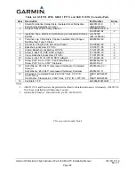
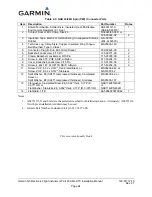
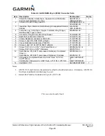
The tables below list the parts required to complete the assembly of the G5, GMU 11, GAD 29/29B, and
GAD 13 wiring harness connectors. Some of the parts required for this installation are included in the
connector kit, and some are to be provided by the installer. See the notes below the tables for parts that
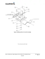
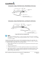
are included in the connector kit. The Garmin connector backshell gives the installer the ability to easily
terminate shield grounds at the connector backshell as shown in and Figure 4-50. Numbers referenced
in Figure 4-49 and Figure 4-50 correspond to items listed in Table 4-4, Table 4-5, and Table 4-6.
This area intentionally blank

