Garmin G5 Electronic Flight Instrument Part 23 AML STC Installation Manual
190-01112-10
Rev. 21
Page 242
D.3.1 Overbraid Termination Methods
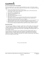
Overbraid must be terminated with an appropriate lug by one of the two following approved methods.
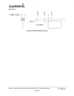
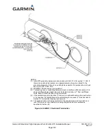
Whichever method is used, overbraid pigtail length must not exceed two inches. Refer to Figure 6-26.
Method A
1.
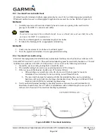
Carefully separate overbraid wire strands by hand to create an opening in the overbraid for
passage of the GMU 11 connector and cables.
CAUTION
Do not cut an opening in the overbraid strands. Loose overbraid wire ends can chafe the cable
and cause the GMU 11 to malfunction.
2.
Trim the overbraid pigtail to a maximum length of two inches.
3.
Terminate the braid pigtail in an appropriate terminal lug.
Method B
1.
Comb out a maximum of two inches of overbraid pigtail.
2.
Twist the pigtail and terminate it in an appropriate terminal lug.
D.3.2 Overbraid Terminal Bonding
Electrical bond preparation for all aluminum-to-aluminum interfaces must be done in accordance with
SAE ARP1870 section 5.1 and 5.5. The overbraid terminal lug must be electrically bonded to a #10 stud
installed in accordance with AC43.13-1B Section 11-189, as well as the following restrictions:
1.
If possible, use an existing tooling hole to install the stud.
2.
If no suitable tooling hole exists, use an existing fastener (#10 or larger).
3.
If there is no suitable fastener, install a new #10 stud as follows:
a.
When adding a new stud hole to the rib, the center of the hole must be located a
minimum of one inch away from any existing, non-stiffened rib hole.
b.
The new stud hole must be located such that the terminal lug face, neck, or attaching
hardware will not intrude into the flange bend radius of any rib edge or stiffened rib hole.
Refer to SAE AS25036 for terminal lug dimensions.
4.
Verify overbraid terminal bonding by checking resistance between the overbraid and the rib.
Resistance should be less than 2.5 mΩ. For installations with overbraid length in excess of 10-
inches refer to Section 4.5 for electrical bonding requirements.
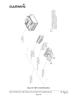
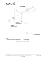
Figure 6-25 GMU 11 Overbraid Installation

