
Garmin G5 Electronic Flight Instrument Part 23 AML STC Installation Manual
190-01112-10
Rev. 21
Page 37
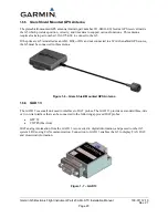
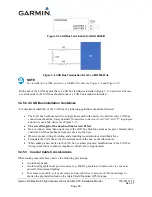
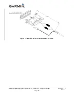
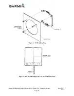
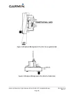
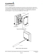
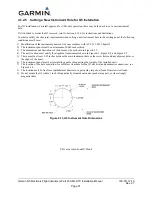
Figure 3-7 GAD 29B Inline Transformer Mounting Instructions
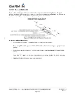
3.4.11
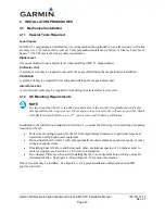
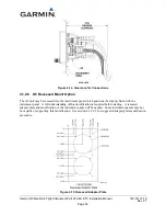
G5 Resistor and Diode installation
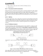
There are two methods of component installation for the required resistors:
•
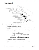
Method A should be used for resistor installations utilizing 120Ω CAN cable and shielded
twisted-pair cable MIL-C-27500 installations that do not use the G5 as a CAN bus terminator, see
Figure 3-8 and Figure 3-9.
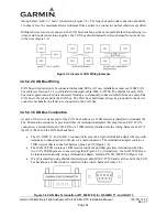
•
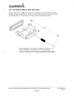
Method B should be used for resistor installations that use the G5 as a terminator and are utilizing
shielded twisted-pair cable, MIL-C-27500, see Figure 3-10 and Figure 3-11.
•
Figure 3-8 and Figure 3-13 show the buildup and installation requirements for the G5 power
diode. This does not depend upon what type of wire is used for the CAN bus.


