Garmin G5 Electronic Flight Instrument Part 23 AML STC Installation Manual
190-01112-10
Rev. 21
Page 106
5
SYSTEM INTERCONNECTS
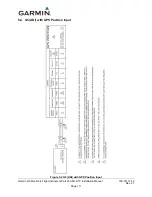
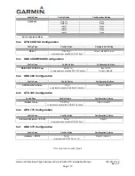
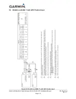
This section will provide the specific wiring interconnects for the various configuration possibilities for
the G5 Attitude indicator and G5 DG/HSI installations. Each installation contains the specific G5 and or
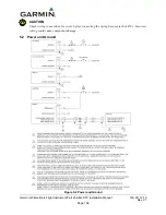
GPS/VHF Navigator configuration table. Power and Ground wiring is identical for each installation and
is only shown in Figure 5-2.
NOTE:
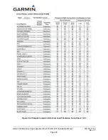
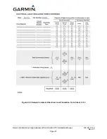
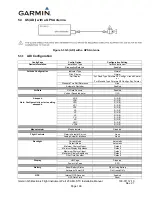
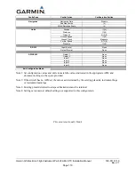
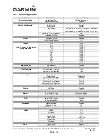
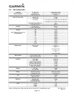
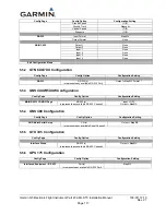
The configuration tables are presented in order as the configuration pages on the G5 are
presented. To make configuration of the G5 easier configure the ARINC 429 and or RS-232
options first. This allows for hidden configurations that require the ARINC 429 or RS-232
options to be selected as appropriate.
NOTE:
For the interconnects diagramed in this section, all navigators are approved for interfacing with
one another in a dual navigator configuration. Please refer to the specific navigator installation
manual for dual unit interconnects.
This area intentionally blank

