Garmin G5 Electronic Flight Instrument Part 23 AML STC Installation Manual
190-01112-10
Rev. 21
Page 143
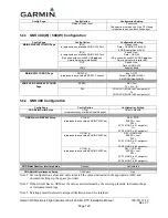
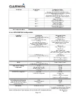
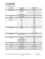
5.11.5
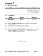
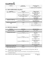
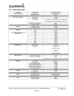
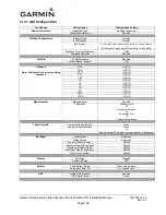
GNS 480 Configuration
Config Page
Config Option
Configuration Setting
GND Maint Serial Setup
CH (x)
(x represents any available Serial Channel)
Output = MapMX
GND Maint ARINC 429 Setup
CH In (x)
(x represents any available ARINC 429 Port)
SEL = EFIS
SPEED = Low
SDI =
SYS1 (If GNS is #1 navigator)
Or
SYS2 (If GNS is #2 navigator)
CH Out (x)
(x represents any available ARINC 429 Port)
SEL = GAMA 429
SPEED = Low
SDI =
SYS1 (If GNS is #1 navigator)
Or
SYS2 (If GNS is #2 navigator)
CH Out (x)
(x represents any available ARINC 429 Port)
SEL = VOR / ILS
SPEED = Low
SDI =
SYS1 (If GNS is #1 navigator)
Or
SYS2 (If GNS is #2 navigator)
GND Maint Resolver Interface Setup
Resolver
Not Installed
GND Maint Miscellaneous Setup
CDI Select
Use
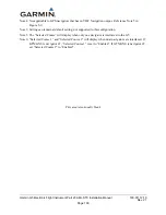
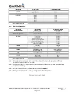
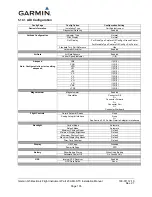
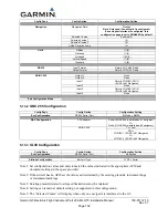
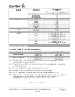
Note 1: Set configuration values and units to match the values indicated in the appropriate AFM and
document settings in the space provided.
Note 2: If the aircraft has no AFM set the values as determined by the existing placards, instrument bugs
or instrument markings.
Note 3: Existing placards related to airspeed limitations must be retained.
Note 4: Setting can remain at default setting, not supported in this configuration.
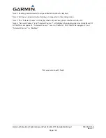
Note 5: The “Selected Course” will display when only one navigator is interfaced to the G5.
Note 6: “Selected Course 1” and “Selected Course 2” will display when dual navigators are interfaced. If
GTN/GNS is navigator #1, “Selected Course 1” is set to “Enabled”. If GTN/GNS
is navigator #2,
set “Selected Course 2” to “Enabled”.
This area intentionally blank

