
Garmin G5 Electronic Flight Instrument Part 23 AML STC Installation Manual
190-01112-10
Rev. 21
Page 41
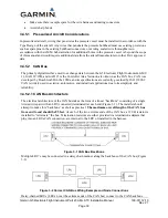
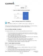
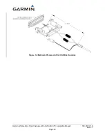
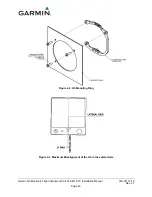
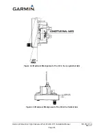
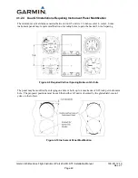
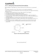
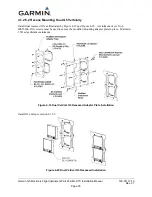
Figure 3-11 Method B Placement of CAN Bus Components
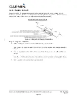
Steps for component installation:
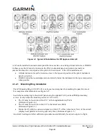
1.
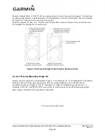
Create resistor buildups as shown in Figure 3-10.
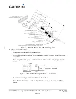
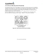
2.
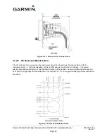
Solder resistor buildups together as shown in the above figure per AS4461. A simplified circuit is
shown below.
Note: Acceptable solder types are SN60 or SN63. Clean flux residues using an appropriate flux
cleaner.
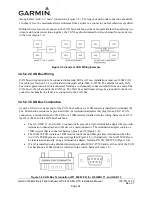
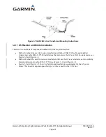
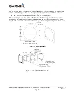
Figure 3-12 Wire P/N M27500 Simplified Resistor connections
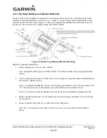
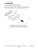
3.
Secure the resistors together in the wire bundle as shown above.
Note: The “-Z” character in the cable tie P/N is for color, color of cable tie is the installer’s
choice.


