Garmin G5 Electronic Flight Instrument Part 23 AML STC Installation Manual
190-01112-10
Rev. 21
Page 44
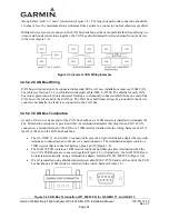
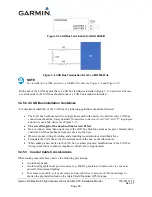
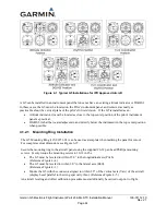
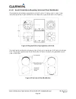
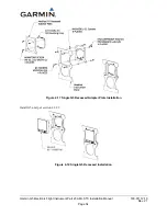
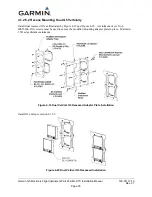
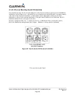
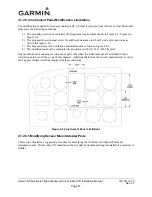
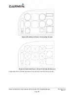
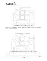
Figure 4-1 Typical G5 Installations for IFR Approved Aircraft
A G5 can be installed in an instrument panel that does not have an existing attitude indicator or DG/HSI.
In these cases, the G5 must be located on the Pilot’s instrument panel, and centered as nearly as
practicable about the vertical plane of the pilot’s forward vision. If the G5 is installed as an;
•
Attitude indicator, it must be located as close to the top center position of the pilot’s instrument
panel as practical.
•
DG/HSI, it shall be located adjacent to and directly below the instrument in the top center position
when possible.
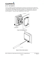
4.1.2.1 Mounting Ring Installation
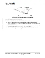
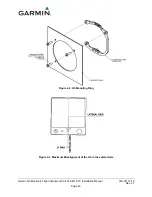
The G5 Mounting Ring (115-02251-03) can be used as a template when marking the panel for cutout.
For complete cutout dimensions see Figure 6-15.
Secure the mounting ring to the aircraft panel using the supplied #6-32 pan head Phillips mounting
screws. Evenly torque the mounting screws to 10-12 in-lbs.
•
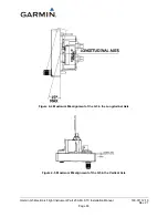
The G5 must be leveled to within 15.0° in the longitudinal axis (Pitch).
(Reference Figure 4-4 )
•
The G5 must be leveled to within 2.0° in the lateral axis (Roll).
(Reference Figure 4-3 )
•
Mount the G5 with the connector aligned to within 1.0° of the vertical axis (Yaw) of the aircraft
(display bezel parallel to the wing spar carry thru). (Reference Figure 4-5 )
An aircraft leveling and offset calibration procedure must additionally be carried out prior to flight.

