Garmin G5 Electronic Flight Instrument Part 23 AML STC Installation Manual
190-01112-10
Rev. 21
Page 18
1.6.1.6 Standby Battery
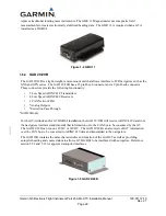
The standby battery is required. The G5 has an externally mounted lithium – ion battery that sustains the
G5 flight display with up to 4 hours of emergency power.
Figure 1-2 G5 Standby Battery
1.6.1.7 G5 Attitude Interfaced to GMU 11
The GMU 11 magnetometer can be installed as an optional interface for a standalone G5 attitude display.
This will allow the display of heading on the attitude display in place of track, but would not allow the
removal of the existing DG.
1.6.1.8 G5 Attitude Interface Summary
The G5 Electronic Flight Instrument when configured as an attitude indicator in this STC installation
uses 14VDC or 28 VDC power, ground, RS-232, CAN bus, and coax connection for the Glare Shield
Mounted GPS Antenna. The following list is a summary of interfaces used by the G5 Attitude indicator.
•
Aircraft Power and Ground
•
Aircraft Pitot/Static
•
GPS Coax connection
•
One RS-232 connection
•
One CAN bus connection
•
Standby battery
1.6.1.9 G5 Attitude Power and Ground Interface Summary
The G5 uses 14VDC or 28 VDC power and aircraft ground. Reference Section 5 for wiring details.
1.6.1.10 G5 Attitude Pitot/Static Interface Summary
The G5 requires pitot and static inputs for the altitude and airspeed functions. Reference Section 4.1.5
for installation specifics.

