34
Part #: GAR_IOM_ 4532522 Rev 08—6/17
Installation
Section 2
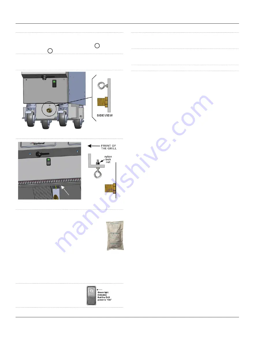
6. Attach one of the spring-loaded hook to the bracket
on the wall and the other end to the eye-bolt (grill).
adjust the proper distance of the cable 1 and tight
both clamps 2 to secure the both cables
7. Test straining cable by moving the grill, movement of
the grill must not place any strain on the connector or
quick disconnect device or its associated piping.
Figure A - one (1) platen
Figure B - two & three (2&3) platen
“Desi Pak” bags from the grill:
•
Desi Pak bags are only intended to be
left inside the grill during shipment and
equipment storage. Desi Pak are designed
to protect the electronic components
by controlling humidity levels within the
equipment.
•
Garland highly recommends these bags remain in
the equipment while the grills are in storage or not in
operation
Removing “Desi Pak” bags from the grill:
1. Turn the clamshell grill
Green Power Main Switch OFF
.
(green light off )
2. Remove the two phillip screws located on each side of
the front panel below the user interface and store them in
a save place.
3. Gently slightly move the panel up and then away
from the grill, be very careful with the wires and
connectors. Remove the bags.
4. Reinstall cover and tighten the screws.
Gas Connections, and Pipe Sizing:
•
The size of the gas line is very important. If the line is too
small, the gas pressure at the burner manifold will be
low. This will cause slow recovery and delayed ignition.
The incoming gas pressure line should be a minimum of
1-1/2”. A 3platen grill requires a 3/4” connection and a
1platen grill requires a 1/2” connection. The 2platen grill
can have either a 1/2” or 3/4” connection.
•
Before connecting new pipe the pipe must be blown
out to dispose of any foreign particles. These particles
will cause improper operation.
•
When using thread compound, use small amounts on
male threads only. Use a compound that is not affected
by the chemical action of LP gases. Avoid applying
compound to the first two threads to prevent clogging
of the burner orifices and control valve.
•
Have the installer check all gas plumbing with a soap
solution for leaks. DO NOT USE matches, candles or
other ignition sources in checking for leaks.
•
Check the data plate to determine the proper type of
gas before connecting the quick disconnect or piping
from the building gas supply.
•
An incoming gas pressure test nipple is provided on the
incoming gas manifold for pressure checks.
•
Minimum incoming gas pressure for Natural Gas is 6”
W.C. Maximum incoming gas pressure for Natural Gas is
14” W.C.
•
Minimum incoming gas pressure for Propane is 10” W.C.
Maximum incoming gas pressure for Propane is 23” W.C.
•
Burner operating gas pressure can be checked at the
outlet side of the gas valve at the pressure test point.
•
Refer to “Gas Input Specification Chart” for correct
burner manifold pressure based on gas type.
•
To adjust the burner pressure;
a. remove the sealing screw from the pressure spigot
on the outlet side of the gas valve and the connect a
manometer.
b. remove the sealing cap on the gas valve regulator
c. turn on both burners in that lane and set the pressure
by turning the regulator screw.


