background image

Part # P128 Rev 5 (05/29/09)

Page 5

INSTALLATION

Serial Plate Location

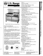
All burner inputs are shown on the Serial/Rating Plate of 
each unit, located on the bottom of the control section near 
the front.

When corresponding with the factory or your local 
authorized factory service center regarding service problems 
or replacement parts, be sure to refer to the particular unit 
by the correct model number (including the prefix and suffix 
letters and numbers) and the warranty serial number. The 
rating plate affixed to the unit contains this information.

We suggest installation, maintenance and repairs should be 
performed by your local authorized service agency listed in 
your information manual pamphlet.

*OUIFFWFOUZPVIBWFBOZRVFTUJPOTDPODFSOJOHUIF

installation, use, care or service of the product, write or call 
our Product Service Department.

This product must be installed by professional personnel as 
specified. Garland/U.S. Range products are not approved or 
authorized for home or residential use, but are intended for 
commercial applications only. Garland / U.S. Range will not 
provide service, warranty, maintenance or support of any 

LJOEPUIFSUIBOJODPNNFSDJBMBQQMJDBUJPOT

General Information

%BNBHF$IFDLDIFDLDBSUPOPSDSBUFGPSQPTTJCMFEBNBHFT
JODVSSFEJOTIJQQJOH"GUFSDBSFGVMMZFYBNJOJOHDIFDLGPS

“Concealed” damage. Report any damage immediately to 
your carrier.

Legs, Casters & Leveling

1.  The unit must be installed on the legs or casters 

provided. A minimum 4 inch (101 mm) air space must 

CFNBJOUBJOFECFMPXUIFVOJUGPSSFRVJSFEBJSøPXUPUIF

burner systems. Avoid placing any objects under the unit 

XIJDIDPVMEPCTUSVDUBJSøPXUPUIFCVSOFSTZTUFNT

 'PSNPEFMTFRVJQQFEXJUIDBTUFSTUIFJOTUBMMBUJPO

shall be made with a connector that complies with the 
Standard for Connectors for Moveable Gas Appliances, 
ANSI Z21.69/CSA 6.16, Addenda Z21.69B-2006/CSA 

# PSMBUFTUFEJUJPOBOEBRVJDLEJTDPOOFDU
EFWJDFUIBUDPNQMJFTXJUIUIF4UBOEBSEGPS2VJDL

Disconnects for Use with Gas Fuel, ANSI Z21.41/CSA 
6.9, Addenda Z21.41A-2005/CSA 6.16A-2005 (or latest 
edition).

 "EFRVBUFNFBOTNVTUCFQSPWJEFEUPMJNJUNPWFNFOUPG

the appliance without depending on the connector and 

RVJDLEJTDPOOFDUEFWJDFPSBTTPDJBUFEQJQJOH5IJTDBO

be accomplished by attaching restraining chains/cables 

GSPNøPPSPSSFBSXBMMUPSFBSPGVOJU

4.  When the unit is installed in its operating location, level the 

unit by adjusting the leveling legs. Use a level across the 
front rear, and sides of each unit.

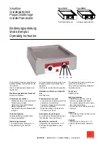
NOTE:  The griddle plate may not rest 
evenly on the unit body if the unit is 
not properly leveled.

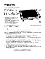
5.  Each caster has a threaded stem 

to aid in leveling only. No caster 
should be adjusted beyond 
a maximum of one-half inch, 
(1/2”/13mm) of exposed thread 

XJUIUIFMPDLJOHOVUUJHIUBHBJOTU

the stand leg, as shown.

Clearances

This unit must be installed in accordance with the following 
clearances in order to provide proper operation and 
servicing of the appliance. Also, it is recommended that the 
unit be installed with sufficient clearance. See chart below.

Clearances

Sides

#BDL

Left Right

Combustible 

6” 

(152mm)

6” 

(152mm)

6” 

(152mm)

Noncombustible  

0”

0”

0”

Service 

/PU3FRVJSFE

Type of Floor or Base

Combustible

Gas Connections

1.  A readily accessible gas shut-off valve is provided on each 

unit, attached to the main manifold under the unit. Gas 
supply connection must be made with minimum 3/4 inch 
NPT pipe. Larger than 3/4 inch (19 mm) supply pipe may 

CFSFRVJSFEXIFOBMPOHSVOPGTVQQMZQJQFJTOFDFTTBSZ

Consult the pipe capacity tables in the installation code.

1

/2"

(

1

3mm)

MAX

Summary of Contents for CG-24R

Page 1: ...636 3903 GARLAND COMMERCIAL RANGES LTD 1177 Kamato Road Mississauga Ontario L4W 1X4 CANADA Phone 905 624 0260 Fax 905 624 5669 Part P128 Rev 5 05 29 09 2005 Garland Commercial Industries LLC FOR YOUR...

Page 2: ...ould expose you to airborne particles of glass wool ceramic fibers Inhalation of airborne particles of glass wool ceramic fibers is known to the state of california to cause cancer Operation of this p...

Page 3: ...Electrical Connection 6 Ventilation 6 OPERATION INSTRUCTIONS 7 Lighting Instructions 7 Shut down Instructions 7 ADJUSTMENTS 8 Thermostat Temperature Verification 8 MAINTENANCE CLEANING 9 Stainless St...

Page 4: ...8 965mm t WPMU BNQT TJOHMF phase t 4FF JMMVTUSBUJPO GPS GVSUIFS specifications size statistics FRONT VIEW Model CG 48R Optional Stand Finished Floor Grease Drawer s 2 3 Units One 4 5 6 Units Two Avail...

Page 5: ...FRVJQQFE XJUI DBTUFST UIF JOTUBMMBUJPO shall be made with a connector that complies with the Standard for Connectors for Moveable Gas Appliances ANSI Z21 69 CSA 6 16 Addenda Z21 69B 2006 CSA PS MBUFT...

Page 6: ...VSOFST BSF PQFSBUJOH DIFDL UIF reading on the manometer If not in accordance with the pressure specified on the Serial Rating Plate adjust the combination valve regulator accordingly When satisfied wi...

Page 7: ...FO UVSO UIF NBJO QPXFS TXJUDI CBDL UP i0 w 5 When the green indicators for their respective zones are illuminated turn the zone power switch for each zone to ON and set the thermostats to the desired...

Page 8: ...FOUT 2 Place the surface temperature probe in the locations indicated on Diagram A Watch the amber indicator for the zone being measured When the amber indicator is ON the burner for that zone is on W...

Page 9: ...step 2 3 The griddle is now seasoned and ready for use Cleaning Instructions After Each Use 1 Using a traditional 64mm 76mm 2 3 scraper or spatula scrape the griddle surface to remove food particles a...

Page 10: ...orrosive and can cause pitting of the griddle 2 Do not allow metal utensils Spatula scraper etc to OJDL BOE PS EFOU UIF TVSGBDF PG UIF HSJEEMF 5IF FEHFT PG these utensils are sharp and will create div...

Page 11: ...DIFDL GVTF CSFBLFS Is Manual Gas Valve turned to ON Turn Manual Gas Valve to ON Is Main Power switch indicator illuminated but zone indicators OFF Turn Main Power switch to OFF wait 5 minutes then tu...

Page 12: ...Pi ce n P128 Rev 5 05 29 09 Page 13...

Page 13: ...ur Le robinet manuel de gaz est il ouvert Ouvrir le robinet manuel de gaz L interrupteur g n ral est il allum mais les indicateurs de zone teints Mettre l interrupteur g n ral en position d arr t pend...

Page 14: ...on conomise l nergie et on emp che la plaque de surchauff er 3 R duire la temp rature pendant les p riodes de ralenti En r duisant la temp rature ou en teignant certaines sections pendant les p riode...

Page 15: ...iff on propre appliquer une fi ne couche d huile friture sur la surface du gril 3 Retirer le tiroir graisse le vider et le laver soigneusement avec un d tergent doux et de l eau Recommencer Instructio...

Page 16: ...grain afi n d viter de rayer le m tal Laver une petite surface la fois rincer la surface lav e avec une ponge tremp e dans un produit d sinfectant et s cher avec un chiff on doux propre avant que la s...

Page 17: ...0 F saisir fermement le cadran du thermostat ne pas modifi er le r glage de 360 F et desserrer la vis de r glage du cadran de fa on ce que le cadran puisse tourner librement sur l axe du thermostat To...

Page 18: ...arri re de l appareil et viter galement les ventilateurs muraux qui cr ent des courants d air dans la pi ce INSTRUCTIONS D UTILISATION Instructions D allumage Des moyens ad quats doivent tre pr vus po...

Page 19: ...ignal tique Pour acc der aux bouts unis d essai de pression placer en position d arr t l interrupteur g n ral d alimentation et tous les interrupteurs de zone comme pr caution de s curit et abaisser l...

Page 20: ...e libre d au moins 4 pouces 101 mm doit tre maintenu sous l appareil pour l alimentation en air des syst mes de br leurs viter de placer des objets sous l appareil car cela pourrait obstruer l aliment...

Page 21: ...CG 48R 120 000 35 00 3 4 Po 625 284 CG 60R 150 000 44 00 3 4 Po 765 348 CG 72R 180 000 52 70 1 Po 995 411 NOTES D INSTALLATION INDIQUER LE TYPE DE GAZ CARACT RISTIQUES LECTRIQUES D gagements Par Rapp...

Page 22: ...ctriques 6 Ventilation 7 INSTRUCTIONS D UTILISATION 7 Instructions D allumage 7 R GLAGES 8 V rifi cation De La Temp rature Du Thermostat 8 Instructions D extinction 8 MAINTENANCE ET NETTOYAGE 9 Acier...

Page 23: ...si res de laine de verre fibres c ramiques L inhalation de ces particules de laine de verre ou de fibres c ramiques est reconnue par l tat de Californie comme causant le cancer L utilisation de ce pro...

Page 24: ...7 Kamato Road Mississauga Ontario L4W 1X4 CANADA T l phone 905 624 0260 T l copieur 905 624 5669 Enodis 5E Langley Station Ro T l phone T l copieu Pi ce n P128 Rev 5 05 29 09 2005 Garland Commercial I...

Reviews: