13–10–613 SP Page 46
cal connection to the main compressor unit. Connect-
ing piping and wiring are furnished by the user. See
“Installation”, Section 2, page 8.
Do not obstruct the air flow to and from the oil cooler.
Allow two (2) feet clearance on all sides of the oil cooler.
See FIGURE 2–2, Section 2, page 8, for cooling air
flow requirements. Keep both faces of the oil cooler
core clean for efficient cooling of the compressor oil. Oil
cooler malfunctions may be traced by checking oil
pressure drop through the cooler; check by installing
pressure gauges at fittings in the inlet and outlet oil pip-
ing near the end of the cooler. At normal operating air
service pressures (65 to 150 psig), with the unit warm,
a pressure drop of 2 to 25 psig can be expected be-
tween the inlet and outlet side of the cooler. The con-
troller will show the reservoir temperature which is the
air temperature in the reservoir and the approximate oil
temperature into the thermal mixing valve.
An oil filler stand pipe and plug must be located in the
piping on the oil cooler module for ease of filling the oil
cooler when it is mounted at a distance from the com-
pressor unit. When filling a remotely mounted oil cooler,
be sure all lines to and from the compressor unit are
also filled to prevent excessive drawdown of the oil sup-
ply in the oil reservoir. A vent line should be installed be-
tween the oil cooler and compressor oil reservoir as an
aid in filling and to prevent siphoning.
HEAT EXCHANGER (OIL) PIPING – All remote ele-
vated cooler applications must be sent through Engi-
neering for approval and for recommending the pipe
size. A special control group will be mounted on the
package at the factory. This group controls the oil stop
valve as well as not allowing the machine to run un-
loaded.Kit number EAU68133 includes the oil stop
valve, check valve and flanges and must be installed on
all remote elevated coolers per FIGURE 5–5, page 45,
and the following instructions.
Remote mounted elevated coolers
have a maximum pipe length of 30 feet
(each way) and a maximum height of
20 feet with a minimum of fittings. En-
gineering will review all remote ele-
vated cooler applications and recom-
mend pipe size on an individual basis.
Customer Service should include the
engineering recommendation in the
special order sent to Engineering.
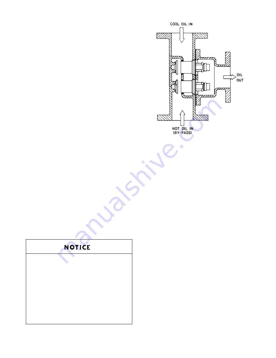
FIGURE 5–6 – THERMOSTATIC MIXING VALVE ELEMENT
B75188
1.
Mount the check valve (90J113).
2.
Mount the drain valves in the lowest section of the
pipe on each side of the cooler connections.
3.
Mount the oil stop valve (90AR243) in the line after
the thermal mixing valve as shown.
Modifications to the control lines will be made at the fac-
tory to control the oil stop valve. Air to the oil stop valve
must come from the dry side of the reservoir cover, then
through the 3–way pneumatic valve. Control air to the
valve must come from the line between the tee and the
orifice in the blowdown muffler line. When the machine
blows down, it will activate the pneumatic valve which
will shut off the air and vent the line between the pneu-
matic control valve and the oil stop valve to the atmo-
sphere. This will shut the oil stop valve and prevent ex-
cessive oil from running into the reservoir. Failure to
install these parts could result in high oil carryover and
cause the machine to shutdown on high discharge tem-
perature.
THERMAL CONTROL (THERMOSTATIC MIXING)
VALVE (FIGURE 5–6) on current units is installed in
the system as shown in FIGURE 5–1, page 40. This
valve is used to control temperature of the oil in both
air–cooled radiator and water–cooled heat exchanger
type oil cooler systems. The element is so designed
that a portion of the oil can flow through the oil cooler
at all times. On start–up with unit cold, element is open
to bypass, allowing oil to pass directly from the reser-
voir to compressor during warm–up. As oil warms, ele-
ment gradually closes to the bypass allowing more of
Summary of Contents for ELECTRA-SAVER EAYQ E
Page 15: ...13 10 613 SP Page 6 DECALS 206EAQ077 212EAQ077 218EAQ077 211EAQ077 207EAQ077 ...
Page 16: ...13 10 613 SP Page 7 DECALS 216EAQ077 217EAQ077 222EAQ077 221EAQ077 208EAQ077 ...
Page 31: ...13 10 613 SP Page 22 FIGURE 4 2 FLOW CHART FOR SET UP PROGRAMMING ...
Page 48: ...13 10 613 SP Page 39 FIGURE 4 13 WIRING DIAGRAM 202EAY546 Ref Drawing ...
Page 75: ......


