13–10–613 SP Page 13
HEAT EXCHANGER
Water Temperature to Heat Exchanger
Approximate
Rated
Gallons/minute
Maximum
Water Pressure
Pressure
Water Flow
Drop @ Maximum
Size
PSIG
60
_
F.
70
_
F.
80
_
F.
90
_
F.
GPM
Flow (PSI)
350 HP
ALL
33
42
56
83
120
21.0
400 HP
ALL
38
48
64
95
120
21.0
500 HP
ALL
48
60
80
119
130
17.0
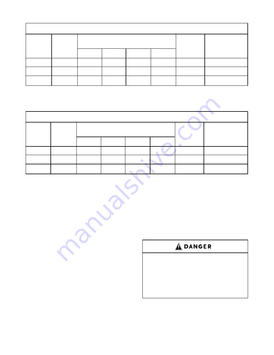
FIGURE 2–7 – HEAT EXCHANGER (OIL COOLER) APPROXIMATE WATER FLOW
The maximum water flow shown is allowable through the heat exchanger.
FIGURE 2–8 – AFTERCOOLER APPROXIMATE WATER FLOW
AFTERCOOLER
Water Temperature to Aftercooler
Approximate
Rated
Gallons/minute
Maximum
Water Pressure
Pressure
Water Flow
Drop @ Maximum
Size
PSIG
60
_
F.
70
_
F.
80
_
F.
90
_
F.
GPM
Flow (PSI)
350 HP
ALL
8.4
10.5
14.0
21.6
100.0
10.0
400 HP
ALL
9.4
11.7
15.6
23.5
100.0
10.0
500 HP
ALL
11.3
14.1
18.8
29.0
100.0
10.0
Water flow rates (gpm) are based on 100
_
F water temperature out of cooler. Maximum water flow shown is the maximum
allowable flow through aftercooler.
cleaned on the inside to prevent dirt or scale from enter-
ing the compressor. If welded construction is used,
the line must be shot blasted and cleaned to remove
welding scale. In either case, the inlet line must be
coated internally by galvanizing or painting with a mois-
ture and oil–proof sealing lacquer. The inlet line should be
the full size of the inlet opening on the compressor. If
an extra–long line is necessary, the pipe size should be
increased according to Inlet Line Length Chart,
FIGURE 2–6, page 12.
Accessibility for inlet air filter servicing must be consid-
ered when relocating the filters from the unit to a remote
location.
DISCHARGE SERVICE LINE – The discharge service
line connection on water–cooled units with aftercooler
is made at the moisture separator. On air–cooled units
and water–cooled without aftercooler, the connection
is made at the pipe nipple located behind the instru-
ment panel. When manifolding two or more
Electra–Saver units on the same line, each unit is iso-
lated by the check valve in the unit discharge line.
If an Electra–Saver unit is manifolded to another com-
pressor, be sure the other compressor has a check
valve in the line between the machine and the manifold.
If an Electra–Saver and a reciprocating compressor
are manifolded together, an air receiver must be lo-
cated between the two units.
Discharge air used for breathing will
cause severe injury or death.
Consult filtration specialists for
additional filtration and treatment
equipment to meet health and safety
standards.
WATER PIPING (Water–Cooled Heat Exchanger
Models Only) – On machines equipped with water–
cooled heat exchangers, the water inlet and outlet con-
Summary of Contents for ELECTRA-SAVER EAYQ E
Page 15: ...13 10 613 SP Page 6 DECALS 206EAQ077 212EAQ077 218EAQ077 211EAQ077 207EAQ077 ...
Page 16: ...13 10 613 SP Page 7 DECALS 216EAQ077 217EAQ077 222EAQ077 221EAQ077 208EAQ077 ...
Page 31: ...13 10 613 SP Page 22 FIGURE 4 2 FLOW CHART FOR SET UP PROGRAMMING ...
Page 48: ...13 10 613 SP Page 39 FIGURE 4 13 WIRING DIAGRAM 202EAY546 Ref Drawing ...
Page 75: ......


