TR-CL180 Lens Controller - User Manual
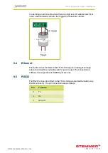
In operating environments where there is a high level of radiated electrical
noise, use a shielded cable for the trigger input as shown below:
9.4
Ethernet
The RJ45 connector fitted to the TR-CL180 requires a straight-through
cable to connect to a network switch, hub or router. The connection is
10Base-T and operates at 10MBits per second.
9.5
RS232
The RS232 connection fitted to the TR-CL180 is a standard female 9-way
DSUB connector. The pin connections are as follows:
Pin
Function
2
Tx
3
Rx
5
Ground
—
12
—
TR-CL180 Lens Controller - User Manual
9.6
Connectors (general)
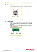
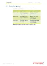
The connectors required to mate with the TR-CL180 controller’s
connections are as follows:
Connector
Description
Suppler / Part number
Power input
Würth 351 series 2
way screw terminal
free socket
Würth 691351500002
Farnell 164-1952
Newark 19P1467
Trigger input
Würth 361 series 4
way screw terminal
free socket
Würth 691361100004
Farnell 184-1351
Newark 16T1571
Lens output*
Hirose HR10 6-way
male plug
Hirose HR10-7P-6P(73)
Farnell 107-7704
Newark 97K1594
*Note:
Where possible, use a standard Optotune lens cable.
—
13
—
WWW.STEMMER-IMAGING.COM


