TR-CL180 Lens Controller - User Manual
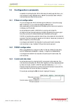
If there is an error, a typical reply might be:
We recommend the host waits for the
>
prompt before sending the next
command; UDP communications are not guaranteed to arrive, so the host
software must be able to deal with lost messages.
When an error occurs, the host may request a reply message to be sent to
it by using the
GT
command.
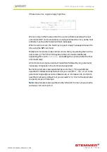
Multiple commands can be entered on one line by separating them with a
semi-colon (
;
). The TR-CL180 replies to the commands individually,
separating them with
<LF><CR>
and adding the
>
prompt after the final
command reply.
All commands comprise a code of two letters followed by any parameter
necessary. All spaces in the command are ignored.
Numeric parameters are separated by a comma (
,
). Time periods are
specified in milliseconds by default, but you can add ‘s’, ‘ms’, or ‘us’ to the
parameter to specify seconds, milliseconds, or microseconds. Current is
specified in amps by default, but you can add ‘A’ or ‘mA’ to the parameter
to specify amps or milliamps.
Note:
All parameters are specified in the ‘USA/UK’ format, where a half is
written as ‘0.5’ and not ‘0,5
—
28
—
TR-CL180 Lens Controller - User Manual
14.4 General commands
Any changes you make using Ethernet commands are not saved
permanently until you send the
AW command.
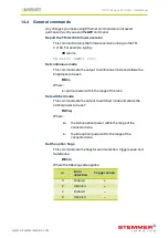
Report the TR-CL180 firmware version
This command returns the firmware version running on the TR-
CL180. For example, typing:
VR returns
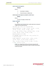
TR-CL180 (HW01) V037
Set continuous mode
This command sets the output to continuous mode and allows the
brightness to be set:
RS1,s
Where:
s = optical power within the range of the lens
Set switched mode
This command sets the output to switched mode and allows the
optical power to be set:
RU1,a,i
Where:
a =
the Active optical power within the range of the
connected lens.
i =
the Idle optical power within the range of the
connected lens.
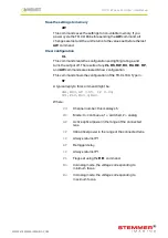
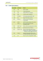
Set the option flags
This command sets the flags for error detection, trigger sense, and
SafeSense:
RE1,m
Where the following code applies:
m
Error
detection
Trigger sense
0
Enabled
+
2
Disabled
+
4
Enabled
–
6
Disabled
–
—
29
—
WWW.STEMMER-IMAGING.COM


