File @ GME c:/mydrawdt/apollo/cir-cont.idw
3
4
5
(C)
(A)
(B)
"B" Module
Rear Valve
"B" Module
Rear Valve
"B" Module
Rear Valve
"B" Module
Front Valve
"A" Module
Front Valve
"A" Module
Rear Valve
A C Mains In
Switched Active Out
Product 1 "A"
FLP. A C Control Junction Box
Product 3 "C"
FLP. A C Control Junction Box
Product 2 "B"
FLP. A C Control Junction Box
Mains Link 89722
Mains Link 89723
Mains Link 89724
"C" Module
Front Valve
"C" Module
Rear Valve
Incoming Pump
Comms.
To PEC Main Processor PCB
(Comms) Refer Pg 28
Connector Block
Dispenser Switched
Active
7 Core Steel Wire Armor
Cable
FST
FLP Junction Box
FLP Barrier
Gland
* = FLP Gland Used
*
*
*
*
*
*
*
*
*
*
*
*
*
Updated 06/05/99
26/11/99 16/02/00
29/01/01 19/02/01
23/03/01
*
*
Head Cabinet
Mains & Switched Active Cabling Layout
_
*
2
1
GN /6
Lights
Optional
5
4
3
2
1
GN
WH
WH
WH
BRO
BLU
GN /6
BLU
GN
GN
GN
WH
WH
WH
BRO
BLU
BLA
BLA
BLU
BLU
GN
GN
GN
WH
WH
WH
BRO
BLU
BLA
BLA
BLU
BLU
GN
GN
GN
WH
WH
WH
BRO
BLU
BLA
BLA
BLU
Layout shown below is used in conjunction only with new version
Asco Valve PVG. Model (note: wiring also unsleeved on this version)
Valve Wiring Option
_
(See Option)
(See Option)
(See Option)
29
Module
Rear Valve
Module
Front Valve
Sol_4
Sol_3
Sol_2
Sol_1
E
N
A
E
N
A
E
N
A
E
N
A
Black
Black
GN
GN
Blue
Blue
Brn
Brn
Summary of Contents for Apollo 3000
Page 1: ...Apollo 3000 Set up Installation Parts Manual...
Page 2: ......
Page 4: ......
Page 15: ...11 Float Switch 89778 Float Swt Mtg Angle only 89749 Float Switch Bracket Assembly...
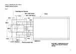
Page 26: ...22 Stage 1 Installation Procedure Sump Column Position Fig 2...
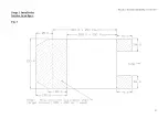
Page 27: ...23 file gme c docum pec apollo2 fig 2 manual doc Stage 1 Installation Service Area Spec Fig 3...
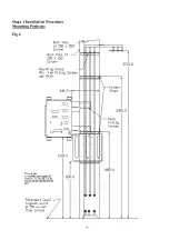
Page 28: ...24 Stage 1 Installation Procedure Mounting Positions Fig 4...
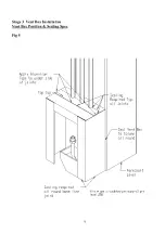
Page 29: ...25 Stage 3 Vent Box Installation Vent Box Position Sealing Spec Fig 5...


