background image

19 

VoIP Telephone. 

6.4. Titan 

Installation 

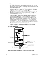
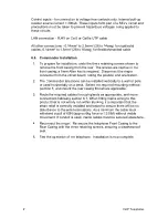
1.  To prepare for installation, open the door (where fitted), then undo the 

four retaining screws to remove the faceplate from the rear enclosure. A 
3mm Allen key is required.   

Caution – take care to support the spring-loaded door whilst open 
to prevent it slamming shut and trapping fingers. 

2.  The Titan telephone is intended for vertical installation to a wall or pole.  

Select the required mounting method (section 5) and mount the rear 
enclosure first where applicable. 

3.  Route the required cables through glands as appropriate, and make 

connections following section 6.5. When fitting mains wiring to this 
product that is not wholly run within trunking, it is important that the 
strain relief is correctly installed and tested to ensure there will be no 
disturbance to the wire terminations. As a minimum the cable must 
withstand a pull of 100N (approx 10kg force or 22.5lbf) without visible 
movement. If conduit is used, mains cables must be secured elsewhere. 

4.  Re-fit the faceplate ensuring a weatherproof seal 

5.  Test the operation of the telephone.  Installation is now complete. 

6.5. Titan 

Connections 

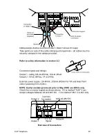
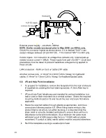
Make the appropriate connections as shown on the diagrams below. 

0V

+

0V

OP2

OP1

-

IP1 IP2 IP3 IP4

48Vdc

1A

-T

RJ45 Network connector
(under back-box)

Power connections
Input connections

Serial port

Output connections

Clamping position
for power and input
cables

Clamping position
for output cables

Back-box

Summary of Contents for Titan

Page 1: ...20 0115 001 Iss 2 Jul 2008 CN33078 001 Installation and User Guide Rugged VoIP Telephone Titan Commander VR and Help Point models GAI TRONICS A division of Hubbell Ltd Titan Commander Vandal Resistant...

Page 2: ...VR and Help Point 15 6 Connections and Installation 17 6 1 General 17 6 2 IMPORTANT SAFETY INFORMATION 18 6 3 Emergency Services warning 18 6 4 Titan Installation 19 6 5 Titan Connections 19 6 6 Comma...

Page 3: ...es are securely clamped in the clamps provided Failure to do so could result in an unsafe installation Take adequate precautions when opening the case or installing If in doubt isolate connections els...

Page 4: ...VoIP Telephone 4 Titan aluminium bodied handset telephone Commander rugged glass reinforced polyester handset telephone...

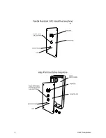
Page 5: ...andal Resistant VR handsfree telephone FRONTPLATE MICROPHONE SPEAKER LED FLUSH 25mm CALL BUTTON Help Point handsfree telephone FRONTPLATE MICROPHONE SPEAKER LED REAR ENCLOSURE PALM OPERABLE STAINLESS...

Page 6: ...password Recommended to prevent unauthorised changes to the phone s configuration Make sure to record these details securely Refer to configuration guide available from website 3 Check for power and...

Page 7: ...oIP telephones Web pages Configuration file Command Line interface CLI Web pages held within the telephone can be accessed over the network using a browser such as Internet Explorer to view and change...

Page 8: ...Select the appropriate sized gland Use the smaller gland for cables diameters 4 7mm 0 16 0 27in Use the larger gland for cable diameters 8 13mm 0 3 0 5in 3 From the outside of the case insert the sel...

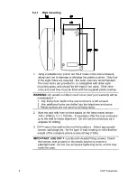
Page 9: ...rear enclosure is left unused 2 Any additional holes are drilled into the telephone enclosure 3 Plastic bushes are not used on all fixing holes 2 Mark the wall with hole centres based on the dimension...

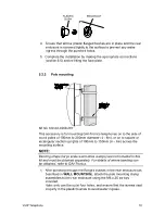
Page 10: ...of 100mm to 200mm diameter 4 8in or on to square or rectangular section uprights of 100mm to 150mm 4 6in across the mounting surface NOTE Banding straps large scale worm drive clamps are not included...

Page 11: ...ones supplied for flush mounting have a slightly different faceplate to those supplied with a rear enclosure in particular the fixing holes are in different positions and there are no corner cut outs...

Page 12: ...mooth surface Do not rely on this gasket to keep water out if mounting directly to rough surfaces such as brickwork in these cases use additional sealant around the edges to ensure a weatherproof seal...

Page 13: ...y making the appropriate connections section 6 5 5 Reconnect the ringer Secure the telephone Front Casing to the Rear Casing 5 3 2 Pole mounting Kit No 100 02 0208 001 This accessory is for mounting G...

Page 14: ...the band may also be sawn off 5 3 3 Desk mounting Rake For horizontal surfaces greater than 150 x 280mm 6 x 11in use the free standing desk mounted method below To provide a rake for convenient opera...

Page 15: ...dentical 5 4 1 Wall Pole Mounting When wall or pole mounted VR and Help Point units must be fitted inside a dedicated rear enclosure The rear enclosure is identical to the Titan enclosure although usu...

Page 16: ...s Select appropriate screws wall plugs etc for the type of wall bearing in mind that the weight of the complete phone is around 1 5kg 3 3lbs 9 Route the cable to within the recess and make connections...

Page 17: ...ng the telephone in inclement weather conditions or by negligence Failure to do so may result in an unsafe condition and will invalidate your warranty Insert each cable through its gland body and tigh...

Page 18: ...ated and and have an overall insulated outer sheath covering both conductors They must be appropriately rated and certified Examples of suitable ratings for PVC cords are IEC 60227 designation H05 VV...

Page 19: ...mains wiring to this product that is not wholly run within trunking it is important that the strain relief is correctly installed and tested to ensure there will be no disturbance to the wire termina...

Page 20: ...oint units if powering from 24Vdc NOTE Earlier models produced prior to May 2008 are 48Vdc only Check the connector legend as shown above If it is marked AUX it can accept voltages between 24 and 48V...

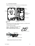
Page 21: ...sition and orientation 2 The Commander telephone can be installed vertically to a wall or pole or used horizontally on a desk Select the required mounting method section 5 and mount the rear casing fi...

Page 22: ...2 5A at 250Vac 1A at 24Vdc Refer to safety information in section 6 2 OP1 OP2 Clamp Clamp Network cable Connection to Output 1 Barrier Cabling example showing connection to Output 1 E OP1 OP2 E NC R L...

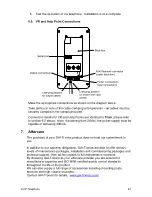
Page 23: ...m the rear enclosure if supplied by undoing the four retaining screws A 3mm Allen key is required 2 VR and Help Point telephones are intended for vertical installation to a wall or pole or flush mount...

Page 24: ...our warranty obligations GAI Tronics are able to offer various levels of maintenance packages installation and commissioning packages and technical support from ad hoc repairs to full maintenance con...

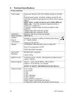
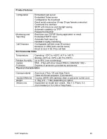
Page 25: ...oving parts Ringer loudness 80dBA 1m Handset Titan Commander Suitable for inductive coupling to Hearing Aids having a T switch position Tested to ETS 300 381 Network 10 100 BaseT Ethernet RJ45 Cat5 or...

Page 26: ...max 20 entries Numbers or URIs with comfort tones Divert to next in list if the call fails Environmental limits Temperature Operating 20 C to 60 C 4 F to 140 F Storing 40 C to 70 C 40 F to 158 F Relat...

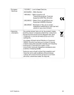
Page 27: ...nce to radio or television reception which can be determined by turning the equipment off and on the user is encouraged to try to correct the interference by one or more of the following measures Re o...

Page 28: ...that the product is classed as Electrical or Electronic Equipment and should not be disposed with other household or commercial waste at the end of its working life The Waste of Electrical and Electro...

Page 29: ...29 VoIP Telephone 9 CE Declaration...

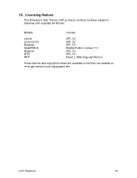
Page 30: ...ensing and copyright as follows Module License u boot GPL V2 Linux kernel GPL V2 Busybox GPL V2 Opal PWLib Mozilla Public License V1 1 Modutils GPL V2 MTD GPL V2 NTP David L Mills Copyright Notice The...

Page 31: ...31 VoIP Telephone...
Page 32: ...Brunel Drive Stretton Park Burton on Trent DE13 0BZ England Tel 01283 500500 Fax 01283 500400 www gai tronics co uk The policy of GAI Tronics is one of continuous improvement therefore the Company res...

Reviews: