21
VoIP Telephone.
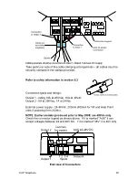
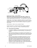
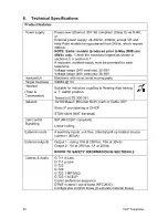
Control inputs - for connection to voltage free contacts only. Internal pull-up
resistor source current = 300uA. These inputs form part of a SELV circuit and
precautions must be taken to prevent hazardous voltages being applied to
these circuits
LAN connection - RJ45 on Cat5 or Cat5e UTP cable
All other connections - 0.14mm² to 2.5mm² (26 to 14awg) for rigid/solid
cables, 0.14mm² to 1.5mm² (26 to 16awg) for flexible/stranded cable.
6.6. Commander
Installation
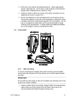
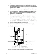
1. To prepare for installation, undo the three retaining screws shown to
remove the front casing from the rear. The screws are captive in the
front casing; a 5mm Allen key is required. Disconnect the ringer
connector from the circuit board, noting the position and orientation.
2. The
Commander
telephone
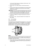
can be installed vertically to a wall or pole,
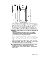
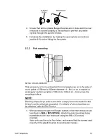
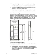
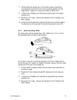
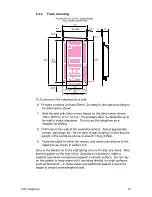
or used horizontally on a desk. Select the required mounting method
(section 5) and mount the rear casing first where applicable.
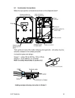
3. Route the required cables through glands as appropriate, and make
connections following section 6.7. When fitting mains wiring to this
product that is not wholly run within trunking, it is important that the
strain relief is correctly installed and tested to ensure there will be no
disturbance to the wire terminations. As a minimum the cable must
withstand a pull of 60N (approx 6kg force or 13.5lbf) without visible
movement. If conduit is used, mains cables must be secured elsewhere.
4. Reconnect the ringer. Re-secure the telephone Front Casing to the
Rear Casing with the three retaining screws, ensuring a weatherproof
seal.
5. Test the operation of the telephone. Installation is now complete.
Summary of Contents for Titan
Page 29: ...29 VoIP Telephone 9 CE Declaration...
Page 31: ...31 VoIP Telephone...

