Commander 1114 VoIP
19
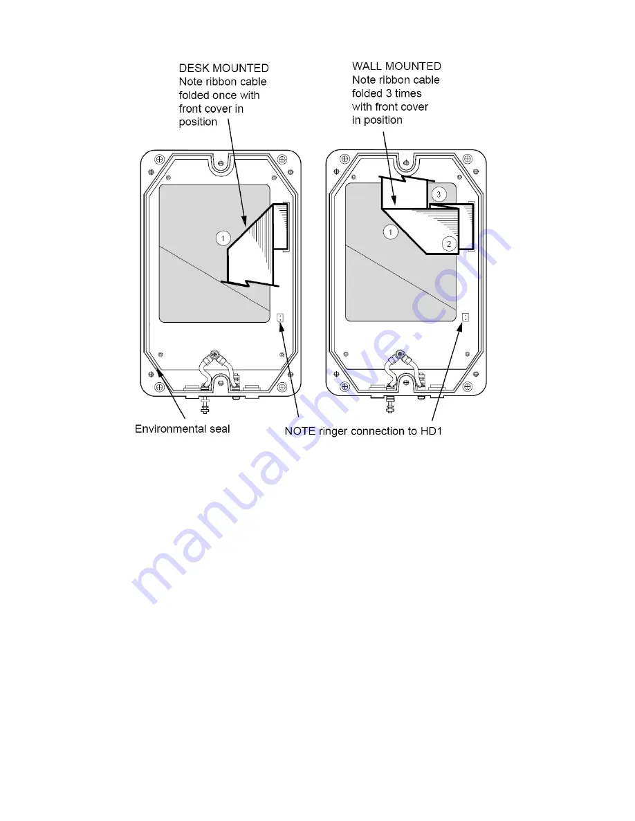
Ribbon cable positions
2. Ensure that the ringer connection is connected from the front case to
HD1 on the main PCB in the rear case.
3. Offer the Front Casing to the Rear Casing, with the ribbon cable
appropriately folded as shown in diagram above; ensure that the cable
will not be trapped when the Front Casing is tightened down. Take
care that all folds are made, the ribbon cable can lay flat and that the
insulation can not become damaged.
Check also that the environmental seal is in position.
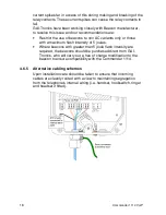
4. Upon installation care should be taken to ensure that incoming cables
are cleanly routed with a view to maintaining segregation from the
telephone's internal wiring (i.e. handset, hookswitch, ringer and
headset if fitted).
5. Tighten the three securing screws firmly.
Summary of Contents for 1114
Page 18: ...Commander 1114 VoIP 17...
Page 31: ...Commander 1114 VoIP 30...


