Commander 1114 VoIP
11
This accessory kit is for mounting GAI-Tronics telephones on to the side
of round poles of 100mm to 200mm diameter, or on to square or
rectangular section uprights of 100mm to 150mm across the mounting
surface. For flat mounting on surfaces greater than 150mm across use
the desk or wall mounted methods as appropriate.
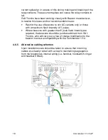
Figure 1 – Pole side mounting
NOTE:
Banding straps (large scale worm-drive clamps) are not included in this
kit and must be obtained separately. For details of where mounting kits
can be obtained, refer to GAI-Tronics .
1. Remove rubber feet from the Rear Casing if fitted. Attach the pole
mounting clamp assemblies to the Rear Casing using the M6 x 25
screws provided.
2. Ensuring that the glands are at the bottom, pass a proprietary
banding strap round each of the pole mounting clamps and the
support pole. Tighten securely.
3. Continue the installation procedure with the connection of individual
wires from the cable as described under sections 4.6 onwards.
4. Secure the telephone Front Casing to the Rear Casing.
5. Re-tighten the straps firmly and trim off any excess band material.
For security the driving head of the band may also be sawn off.
4.5.3
Desk Mounting / Rake
IMPORTANT WARNING:- Risk of impact or falling
This telephone, when used in a desk mounting mode, should be located
on a horizontal, flat non-slip surface. Due to the heavy and robust
construction of the unit, users must take care when using the handset
or headset, not to pull the cord to such an extent as to cause the
telephone to be pulled off the flat surface, and possibly cause damage
or injury to persons or equipment. Therefore it is recommended that the
unit be fixed in position using fixing positions and method detailed in
section 4.5 if there is any risk of the unit being dislodged as described
above.
To provide a 'rake' for convenient operation, the Front Casing may be
turned through 180° before it is fitted to the Rear Casing. Thus the
cable entries are at the rear of the telephone.
1. Ensure that the supplied rubber feet are fitted to the underside of the
Rear Casing if the telephone if not fixed into position.
2. Rotate the Front Casing through180° and fold the keypad ribbon
cable to ensure that it lays flat against the potted block when re-
assembled. Refer to Ribbon cable positions (page 19)
Summary of Contents for 1114
Page 18: ...Commander 1114 VoIP 17...
Page 31: ...Commander 1114 VoIP 30...


