1. INSTALLATION
1-20
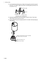
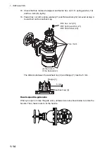
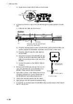
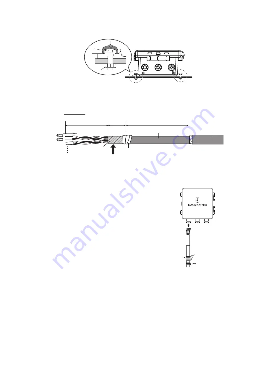
3) Apply silicon rubber to M10 bolts as shown below.
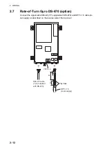
2. Connect the TTYCS-4 cable to the DS-600 through the cable glands for the DS-
605.
1) Fabricate the cable as shown below.
2) Pass the clamping gland, washer (26-003-1607), gasket (26-003-1605) and
washer (supplied as installation materials) onto the cable, in that order.
3) Pass the cable through the cable gland as
shown below.
4) Open the front cover of the DS-605 and con-
nect the ground wire attached inside the DS-
605 to the ground terminal on the rear of the
DS-600.
5) Connect the cables to the DS-600. Refer to
3. Remove each binding head screw from four cor-
ners of the DS-605 and set the DS-600 to the
DS-605. These screws can be discarded.
4. Apply silicon grease to the binding head screws
included in CP66-01731 and fix the DS-600 to
the DS-605 with four binding head screws.
5. Tighten the clamping glands to fix the cables.
6. Apply putty to the cable glands for waterproofing.
7. Connect the ground terminal for the DS-605 to the ground terminal on the hull with
the IV-1.25 sq. wire.
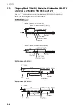
Apply silicon rubber.
Apply silicon rubber.
Seal washer
Seal washer
Nut
Nut
M10 bolt
M10 bolt
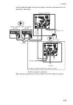
Vinyl seath
80
35
7
Armor
Shield
M3
Vinyl tape
130
TTYCYS-4
Vinyl seath
Fold back and wrap internal shield
and fix it by cable clamp.
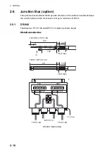
x2
Washer*
Gasket*
TTYCYS-4 cable
{
Clamping gasket
*: Attached inside
the cable gland
Summary of Contents for DS-60
Page 51: ...APPENDIX 1 CALIBRATION AP 3 ...
Page 59: ...8 Mar 2010 Y NISHIYAMA D 1 ...
Page 60: ...18 Dec 2012 Y NISHIYAMA D 2 ...
Page 61: ...18 Dec 2012 Y NISHIYAMA D 3 ...
Page 62: ...D 4 30 Jun 2015 H MAKI ...
Page 63: ...D 5 30 Jun 2015 H MAKI ...
Page 64: ...1 Jul 2011 Y NISHIYAMA D 6 ...
Page 65: ...29 Mar 2011 Y NISHIYAMA D 7 ...
Page 66: ...29 Mar 2011 Y NISHIYAMA D 8 ...
Page 67: ...D 9 30 Jun 2015 H MAKI ...
Page 68: ...D 10 30 Jun 2015 H MAKI ...
Page 69: ...D 11 15 Apr 2016 H MAKI ...
Page 70: ...D 12 15 Apr 2016 H MAKI ...
Page 71: ...D 13 15 Apr 2016 H MAKI ...
Page 72: ...D 14 15 May 2015 H MAKI ...

