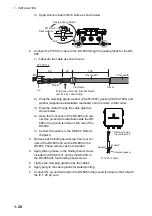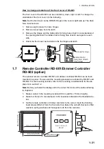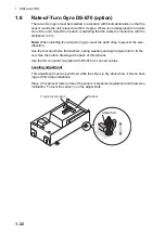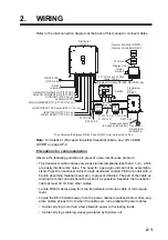
1. INSTALLATION
1-18
1.5
Junction Box DS-640, DS-645A/B (option)
Installation considerations
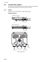
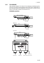
The junction box forms a joint between the distributor and the transceiver unit, and ex-
tends the distance between them to max. 500 m. Install it as below:
• Keep the junction box away from noise-emitting electrical machinery, for example,
electric gen-erator, radio transmitter and TV.
• Do not install the junction box in place of high temperature and humidity.
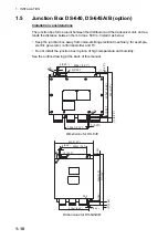
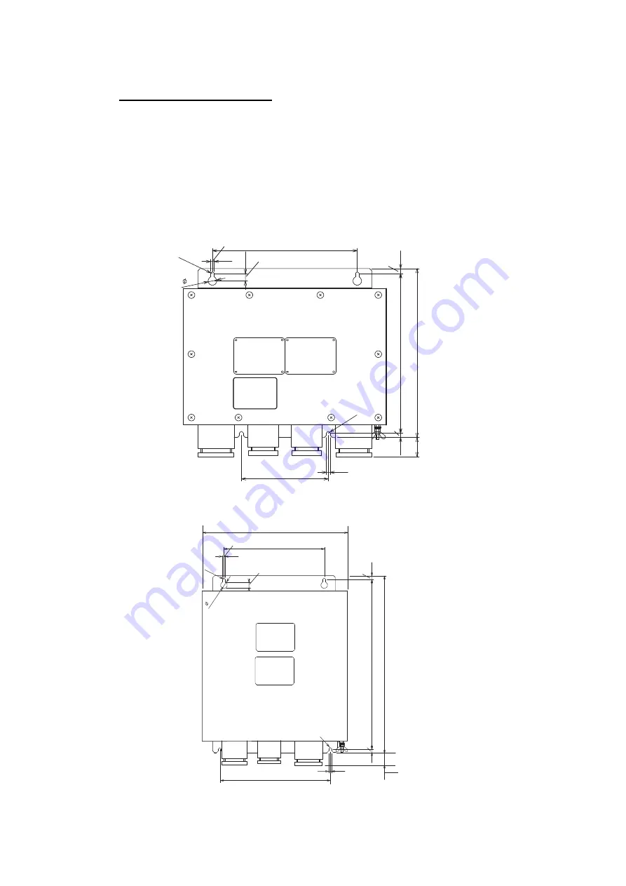
See the outline drawing at the back of this manual.
Dimensions for DS-640
Dimensions for DS-645A/B
200±1 (7.87”)
120±1 (4.72”)
220
±1 (8.66”)
233 (9.17”)
7
(0.28”)
6 (0.24”)
5 (0.20”)
5 (0.20”)
10 (0.39”)
12
R2.5
R2.5
(7) (0.28”)
200±1 (7.87”)
220±1 (8.66”)
)”
9.
11
(
1±
2
0
3
)”
5.
2
1(
7
1
3
7
)”
8
2.
0(
)”
4
2.
0(
6
5 (0.20”)
5 (0.20”)
10 (0.39”)
12
R2.5
R2.5
)”
6
4.
1(
)
7
3(
292 (11.50”)
Summary of Contents for DS-60
Page 51: ...APPENDIX 1 CALIBRATION AP 3 ...
Page 59: ...8 Mar 2010 Y NISHIYAMA D 1 ...
Page 60: ...18 Dec 2012 Y NISHIYAMA D 2 ...
Page 61: ...18 Dec 2012 Y NISHIYAMA D 3 ...
Page 62: ...D 4 30 Jun 2015 H MAKI ...
Page 63: ...D 5 30 Jun 2015 H MAKI ...
Page 64: ...1 Jul 2011 Y NISHIYAMA D 6 ...
Page 65: ...29 Mar 2011 Y NISHIYAMA D 7 ...
Page 66: ...29 Mar 2011 Y NISHIYAMA D 8 ...
Page 67: ...D 9 30 Jun 2015 H MAKI ...
Page 68: ...D 10 30 Jun 2015 H MAKI ...
Page 69: ...D 11 15 Apr 2016 H MAKI ...
Page 70: ...D 12 15 Apr 2016 H MAKI ...
Page 71: ...D 13 15 Apr 2016 H MAKI ...
Page 72: ...D 14 15 May 2015 H MAKI ...

