37
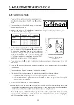
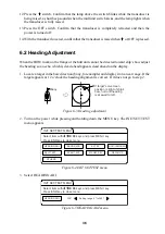
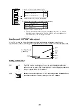
4. Enter heading correction with
←
or
→
referring to the table below for guidance.
Target Location
Correction Setting
Target displayed 30° to port
Set to 30°
Target displayed 30° to starboard Set to 330°
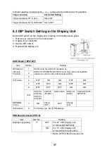
6.3 DIP Switch Setting in the Display Unit
Set the DIP switch on the display unit, referring to the table shown below.
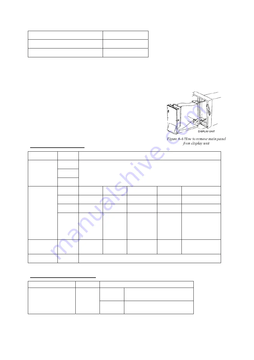
1. Remove six screws from the main panel.
2. Unplug four connectors.
3. Set the DIP switch.
4. Reassemble display unit.
DSW Board (10P6722F)
Item SW
No.
Setting
1
2
ID Code for
Interlock
Function
3
Set ID code for interlock operation of
CSH-21/71/81/82/53/23/73/83 sonar. Any code is acceptable
unless it is used in other interlocked sonars.
4 OFF ON ON OFF
ON
5 OFF OFF ON OFF
ON
6 OFF OFF OFF ON
ON
Unit Code
Unit
CSH-58
(28 kHz)
CSH-53
(28 kHz)
CSH-53
(55 kHz)
CSH-23/24 CSH-73/
83/84
CSH-23F/23FL/
24F/24FL
EEPROM
Check
7 ON
Check
OFF
OFF
Check
ON
Stand Alone
8
For factory use. Set to ON always.
PND Board (10switchP6714)
Item SW
No.
Setting
OFF
For 21” CRT display unit
(CSH-24/24F/24FL/84)
Display unit setting
3*
ON
For 15” CRT display unit
(CSH-23F/23FL/24F/24FL)
*: Set to OFF for the Processor unit.
Summary of Contents for CSH-23
Page 1: ...COLOR SCANNING SONAR MODEL CSH 23 23F 24 24F Back ...
Page 9: ...4 Figure 3 2 Maintenance space example sonar compartment ...
Page 17: ...12 4 WIRING 4 1 Cable Configuration Figure 4 1 Cable configuration ...
Page 53: ...A 4 ...
Page 54: ...A 5 ...
Page 61: ...A 12 ...
Page 71: ...A 22 ...
Page 72: ...A 23 ...
Page 73: ...A 24 ...
Page 74: ...A 25 ...
Page 75: ...A 26 ...
Page 76: ...A 27 ...
Page 77: ...A 28 ...
Page 78: ...A 29 ...
Page 79: ......
Page 80: ...D 2 ...
Page 81: ...Y Hatai D 3 ...
Page 82: ...D 4 ...
Page 83: ...Oct 31 03 D 5 ...
Page 84: ...D 6 ...
Page 85: ...D 7 ...
Page 86: ...D 8 ...
Page 87: ...Dec 10 02 D 9 ...
Page 88: ...D 10 ...
Page 89: ...D 11 ...
Page 90: ...D 12 ...
Page 91: ...D 13 ...
Page 92: ...D 14 ...
Page 93: ...D 15 ...
Page 94: ...D 16 ...
Page 96: ...S 2 ...

