background image

7

Installing hull unit on retraction tank

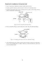
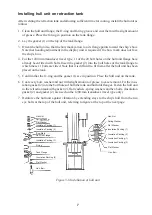
After welding the retraction tank and allowing sufficient time for cooling, install the hull unit as
follows:

1. Clean the hull unit flange, the O-ring and O-ring groove and coat them with a slight amount

of grease. Place the O-ring in position on the tank flange.

2. Lay the gasket (1) on the top of the tank flange.

3. Orient the hull unit so that the bow mark (arrow) on its flange points toward the ship’s bow.

Note that heading adjustment in the display unit is required if the bow mark does not face
the ship’s bow.

4. For the 1200 mm transducer travel type, 11 of the 24 bolt holes on the hull unit flange have

already been fitted with bolts. Insert the gasket (2) into the bolt holes of the tank flange to
which these 11 bolts are fitted. Note that it is difficult to fit them after the hull unit has been
placed on the tank.

5. Confirm that the O-ring and the gasket (1) are in position. Place the hull unit on the tank.

6. Coat every bolt, washer and nut with slight amount of grease to ease removal. Fit the insu-

lation gasket (2) into the bolt holes of both the tank and hull unit flanges. Fasten the hull unit
to the retraction tank with gasket (2), flat washers, spring washers and hex bolts. (Insulation
gasket (2) and gasket (2) are used on the 1200 mm transducer travel type only.)

7. Reinforce the hull unit against vibration by extending stays to the ship’s hull from the two

eye bolts at the top of the hull unit, referring to figure at the top of the next page.

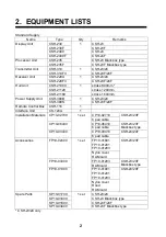
Hex.Nut

Spring Washer

Flat Washer
Insulation Packing (1)

Insulation Packing (2)

Bow Mark

Hull Unit Flange

Insulation Packing (1)

O-ring

Insulation Packing (2)

Tank Flange

Hex. Bolt

Flat Washer

Hex. Nut

Spring Washer

Flat Washer

Insulation Packing (1)

Insulation Packing (2)

Insulation Packing (1)

Insulation Packing (2)

Flat Washer

Hex. Bolt

Figure 3-6 Installation of hull unit

Summary of Contents for CSH-23

Page 1: ...COLOR SCANNING SONAR MODEL CSH 23 23F 24 24F Back ...

Page 2: ... 0798 65 2111 Fax Fax 0798 65 4200 0798 65 4200 FIRST EDITION FIRST EDITION NOV NOV 1997 1997 Printed in Japan Printed in Japan All rights reserved All rights reserved J3 J3 OCT OCT 05 2006 05 2006 Pub No Pub No IME 13040 J3 IME 13040 J3 00080806903 00080806903 00080806903 00080806903 TATA TATA CSH 23 24 F CSH 23 24 F 0 0 0 8 0 8 0 6 9 0 3 0 0 0 8 0 8 0 6 9 0 3 IME13040J30 IME13040J30 IME13040J30 ...

Page 3: ...ed off Improper handling can result in electri cal shock WARNING Install the specified transducer tank in accordance with the installation instructions If a different tank is to be installed the shipyard is solely respon sible for its installation and it should be installed so the hull will not be damaged if the tank strikes an object The tank or hull may be damaged if the tank strikes an object I...

Page 4: ... Fabricating Cables Assembling Connectors 15 4 5 Connection of Transducer Cables 23 4 6 Connection of Interface Unit CS 120A 24 4 7 Connection of Sub display Unit CSH 236 236F Option 29 4 8 Synchronizing Transmission with Other Sonars Echo Sounders 30 4 9 Interlocking Operation with Other Sonar 32 5 CHANGING POWER SPECIFICATIONS 34 6 ADJUSTMENT AND CHECK 6 1 Hull Unit Check 35 6 2 Heading Adjustme...

Page 5: ...DER AD CONVERTER ECHO SOUNDER COLOR VIDEO SOUNDER NET SONDE 100 VAC or PROCESSOR UNIT CSH 235 CSH 235F CSH 230F CSH 23F CSH 23 23F only CSH 2400 CSH 24 CSH 2400F CSH 24F INTERFACE UNIT CS 120A TRANSMITTER UNIT CSH 310 CSH 23 24 CSH 310FII CSH 23F 24F RECEIVER UNIT CSH 220A CSH 23 24 CSH 220FII CSH 23F 24F HULL UNIT CSH 21080 800 mm stroke CSH 21120 1200 mm stroke CSH 21160 1600 mm stroke POWER SUP...

Page 6: ...Supply Unit CSH 380S 1 CSH 23F 24F Remote Control Box CSH 116 1 Interface Unit CS 120A 1 CP10 02710 CP10 02700 6 pair cable CSH 23 23F CP10 06410 CP10 06400 6 pair cable CSH 23 23F Blackbox type CP10 03410 Installation Materials CP10 03400 1 set 6 pair cable CSH 24 24F FP10 01801 FP10 01201 FP10 01203 FP10 02400 Nylon cover RAM card CSH 23 23F FP10 01203 FP10 03000 RAM card CSH 23 23F Blackbox typ...

Page 7: ...able Set with inst materials CSH 1300 000 069 996 For CSH 24 24F 37C Cable 10S1258 000 101 006 7C Cable 10S1259 000 101 007 16P Cable 10S1260 000 101 008 Specify length Handle Assembly OP10 3 006 949 950 Mounting Fixture OP10 9 006 990 040 Automatic Raise Modification Kit CSH 1500 000 068 927 ROM Option Kit A OP10 15 006 998 620 ROM Option Kit B OP10 18 006 998 650 CSH 21081 1 Stroke 800mm 24 kHz ...

Page 8: ... of the retraction tank should be within 600 mm of the keel to prevent a rolling effect Figure 3 1 Hull unit mounting location Select a place where the hull bottom is flat and the draft is sufficiently deep Normally the transducer should protrude at least 500 mm beyond the keel to minimize the effect of air foam and bubbles Select a place where interference from other equipment is minimal The hull...

Page 9: ...4 Figure 3 2 Maintenance space example sonar compartment ...

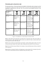
Page 10: ...ottom Note that the length D must be less than 1203 mm Remove within 282 mm from the bottom Note that the length D must be less than 1703 mm Same as left Same as left Figure 3 3 Guidelines for shortening the retraction tank Note 1 In the 800 mm type hull unit more than 297 mm must be removed from the bottom so that the transducer fully protrudes from the tank If more than 382 mm is removed the tra...

Page 11: ... retraction tank allowing space for tightening of bolts and nuts Figure 3 4 How to install reinforcement ribs 4 When an attachment flange is used install reinforcement ribs to the attachment flange Figure 3 5 Installing reinforcement ribs to the attachment flange 5 Add a doubling plate at the location where the retraction tank is welded to the hull bottom The size of the doubling plate is normally...

Page 12: ...ull unit has been placed on the tank 5 Confirm that the O ring and the gasket 1 are in position Place the hull unit on the tank 6 Coat every bolt washer and nut with slight amount of grease to ease removal Fit the insu lation gasket 2 into the bolt holes of both the tank and hull unit flanges Fasten the hull unit to the retraction tank with gasket 2 flat washers spring washers and hex bolts Insula...

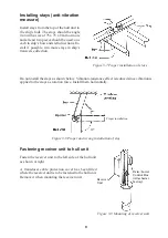
Page 13: ...tance effect is reduced since vibration is applied to the stays as rotation force Install them horizontally Figure 3 8 Proper and wrong installation of stay Fastening receiver unit to hull unit Fasten the receiver unit to the left side of the hull unit as shown at right A transducer cable protection cover has been fitted where the receiver unit is to be fastened to the hull unit Remove it when mou...

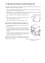
Page 14: ... clearance shown in the outline drawings is ensured Place where the CRT face is within 45 from vertical Mounting the display unit sub display unit 1 Remove the mounting base by unscrewing the two bolts at the front bottom 2 Fix the mounting base to the table with four M10 bolts flat washers spring washers and nuts It is recommended that a rubber mat be placed under the mounting base to absorb vibr...

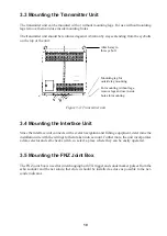
Page 15: ...use inside holes for mounting Figure 3 11 Transmitter unit 3 4 Mounting the Interface Unit Since the interface unit connects with several navigation and fishing equipment determine the installation site with the wirings to them taken into account Furthermore the unit incorporates a data selector and self check switch so select a place where they can be easily operated 3 5 Mounting the FNZ Joint Bo...

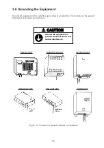
Page 16: ...nd wire The location of the ground terminal of each unit is shown below CAUTION Ground the equipment to prevent electrical shock and mutual interference DISPLAY UNIT TRANSMITTER UNIT RECEIVER UNIT INTERFACE UNIT FNZ JOINT BOX POWER UNIT Figure 3 12 Location of ground terminals on equipment ...

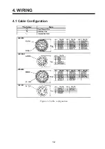
Page 17: ...12 4 WIRING 4 1 Cable Configuration Figure 4 1 Cable configuration ...

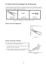
Page 18: ...01 016 Contact Pin 60 8017 0313 00 039 Pin Extractor 06 1877 04 Figure 4 2a Crimping tool contact pin pin extractor How to use the crimping tool How to use the pin extractor If a contact pin is inserted into an incorrect hole on the con nector body remove it with the pin extractor 1 Push the pin extractor into the pin hole from the side opposite to the pin inserting side 2 Push in the head of the ...

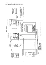
Page 19: ...ERFACE UNIT DISPLAY UNIT 1 REMOTE CONTROL TRANSMITTER UNIT RECEIVER UNIT RAISE LOWER CONTROL BOX POWER UNIT DPYCY 4 Figure 4 3 Location of connectors DPYDY 1 5 1 For blackbox type the processor unit is provided instead of display unit ...

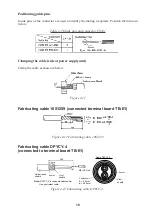
Page 20: ...ation cable 00 8016 038 313 761HV Assembling the 38P connector Shorten the unused wires appropriately and their ends with vinyl tape to prevent short circuit Insulate unused wires with vinyl tape Guide Pin A Guide Pin B Position No Guide Pin A Large Guide Pin B Small Figure 4 5 How to assemble the 38P connector Positioning guide pins Guide pins of the connector identify the mating receptacle Posit...

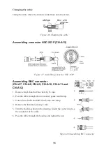
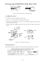
Page 21: ...A9 CN A10 CN A11 and CN A12 1 Remove vinyl sheath of the cable by 15 mm 2 Pass the cable through the nut washer gasket and clamp 3 Unravel the shield and fold it back onto the clamp 4 Remove the insulator leaving 3 mm 5 Trim the shield as shown in the drawing Solder the center chip to the conductor of the cable 6 Pass the cable through the housing and tighten the nut Figure 4 8 Assembling BNC conn...

Page 22: ... outside the connector case 2 Fix the cover 1 taking heed of the cable outgoing direction 3 Dress the wires and fix the cover 2 and 3 Use a fragment of cable sheath to secure the wires at the connector clamp 4 Shorten unused wires appropriately and treat their ends with vinyl tape to prevent short circuit Figure 4 10 Assembling 38P connector ...

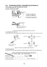
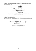
Page 23: ... the cable as shown in below Figure 4 11 Fabricating cable 10S1259 connected terminal board TB E1 Figure 4 12 Fabricating cable 10S1259 Fabricating cable DPYCY 4 connected to terminal board TB E1 M4 YEL x 2 Anticorrosive sheath Armor Vinyl sheath 330 35 30 Conductor S 4 0 mm ø 2 55 mm 2 Vinyl sheath Armor Cable DPYCY 4 Note DPYCY 4 is Japan standard cable Use equivalent cable Figure 4 13 Fabricati...

Page 24: ...ing direction 3 Dress the wires and fix the cover 2 and 3 Use a fragment of cable sheath to secure the wires at the connector clamp 4 Shorten unused wires appropriately and treat their ends with vinyl tape to prevent short circuit Figure 4 15 Assembling 38P connector Positioning guide pins Guide pins of the connector identify the mating receptacle Position them as shown below Table 4 3 guide pins ...

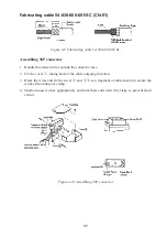
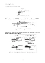
Page 25: ...6 Clamping the cable Fabricating cable 10S1259 connected to terminal board TB B1 Figure 4 17 Fabricating cable 10S1259 Fabricating cable 54 038 000 601 SC CN C2 CN C3 and CN C5 00 8016 020 313 703V CN C4 Figure 4 18 Fabricating cable 54 038 000 601 SC 00 8016 020 000 703V ...

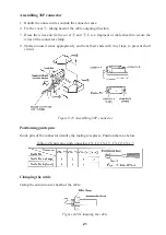
Page 26: ... the wires at the connector clamp 4 Shorten unused wires appropriately and treat their ends with vinyl tape to prevent short circuit Figure 4 19 Assembling 38P connector Positioning guide pins Guide pins of the connector identify the mating receptacle Position them as below Table 4 4 Guide pins and connectors CN C2 CN C3 CN C4 CN C5 Clamping the cable Clamp the anticorrosive sheath of the cable Fi...

Page 27: ... TB D1 in Raise Lower Control Box Figure 4 21 Fabricating cable connected to terminal board TB D1 in Raise Lower Control Box Fabricating cable 10S1259 connected to terminal board TB D2 in Raise Lower Control Box Figure 4 22 Fabricating cable 10S1259 ...

Page 28: ...unit rear view Lead the cable into the receiver unit and clamp it as follows Vinyl tape Ground the cable by cable clamp 1 Use the connector puller supplied to unplug connectors Connector Puller Code No 100 008 460 2 When one or some of the lead wires are severed near a connector cut off all lead wires connected to the connector and solder the XH connector assembly type 10 145 13P supplied as spare...

Page 29: ...e three methods to feed the data Heading data is fed to J205 from A D Converter AD 100 and the speed pulse data to J206 from the speed log Both heading and speed data are fed to J207 or J204 from the CIF line of the CI 30 50 60 NMEA signal is fed to J208 NMEA port or J207 CI NMEA port A D CONV AD 100 INTERFACE CS 120A DISPLAY UNIT CSH 830 ELECTROMAGNETIC LOG DOPPLER SONAR CURRENT INDICATOR Heding ...

Page 30: ...MTW Position fixing Data GGA RMC GLL RMA Speed Data VTG Heading Data VTG HDT Current Data VHW VDR CUR Time Data ZDA Receivable NMEA Sentences from CI NMEA port Same data as NMEA data is received NMEA port has priority Receivable CIF data from CIF port 11 Time Data 21 Dead reckoning Position 24 Loran C fixing Position 28 GPS fixing Position 41 Speed and Heading Data for Dead reckoning 48 Speed and ...

Page 31: ...r picture E S INTERFACE UNIT CS 120A J203 E S VI 1100A Connection 2 Displaying echo sounder picture and FNZ markers by one echo sounder E S J203 E S VI 1100A J202 SONDE INTERFACE UNIT CS 120A SONDE FNZ SONDE FNZ SONDE FNZ 1 2 3 FNZ JOINT BOX CS 170 TB 1 TB 2 J701 J705 TB 1 TB 2 This method is used when the net sonde is installed and both echo sounder and net sonde signals are taken from the same e...

Page 32: ...onnected to temperature sensor Depth Color video sounder Note When a sounder which has digital depth data output is not available the white line signal of a paper recording echo sounder can be used to provide digital depth readout Connect the echo sounder as shown below or as shown in connection 2 or 3 on previous pages and operate the echo sounder front panel controls so that the white line is ef...

Page 33: ...SCREW CLAMP SET SCREW 2cm BRAIDED SHIELD SOLDERING SIDE SOLDERING SIDE CLAMP SHIELDING TAPE WITH CONNECTOR CLAMP FOR GROUNDING WIND VINYL TAPE CONNECTOR CASE SOLDERING WIND SHIELDING TAPE CLAMP FIXING SCREW CLAMP SET SCREW VINYL SHEATH INNER VINYL SHEATH OUTER SOLDER UNUSED CORES AND EARTH TO BRAIDED SHIELD EARTH WIRE 1cm 8cm 2cm BRAIDED SHIELD ARMOR 3 mm Figure 4 30 Fabrication of 10P 7P connecto...

Page 34: ...etting Set DIP switch S1 on the RDCB Board 10P6724 in the sub display unit as follows 10P6724 CN A3 CH 3 CN A1 CH 1 CN A2 CH 2 S1 SW No Used for Function 1 2 3 4 5 6 7 8 Display unit on CH 1 Display unit on CH 2 Display unit on CH 3 Display unit on CH 1 Display unit on CH 2 Display unit on CH 3 ON Turning on sub display unit automatically turns on display unit Don t set OFF because the system does...

Page 35: ...unders To synchronize the transmission of the CSH 23 24 series sonars to that of other sonars or echo sounders wire units as follows Connections Figure 4 33 Connections for synchronizing transmission with echo sounder having current driven KP voltage driven KP ...

Page 36: ...units as follows Figure 4 34 Connections for outputting KP to other sonar or echo sounder Menu setting Set polarity of the KP on the INIT SET TEST menu Set transmission cycle to 0 on data setting window Refer to the operator s manual for operation on the menu ...

Page 37: ...ted on the SYSTEM menu See the operator s manual for further de tails Connections for interlocking functions Two sonars Sonar 1 CN A4 TD H A TD C B RD H E RD C F Sonar 2 CN A4 E RD H F RD C A TD H B TD C P P Figure 4 35 connections for interlocking function of two sonars Three sonars Sonar 1 Sonar 2 TD RD RD TD TD RD Sonar 3 Figure 4 36 Connections for interlocking functions of three sonars DIP sw...

Page 38: ... one remote control box wire units as follows REMOTE CONTROL CONE Board DISPLAY 1 CONE Board DISPLAY 2 CONE Board DISPLAY 3 CN A13 CN A14 CN A13 CN A14 CN A13 CN A14 Connect same pin numbers NH 10P Connect same pin numbers NH 10P Figure 4 37 Connections for interlocking remote control ...

Page 39: ...or 220 VAC To power it by 100 VAC or 220 VAC use step down transformer PT 400 change the trans former taps on the power supply unit as below and connect the ship s mains directly The power supply unit has been set for 100 VAC when delivered F Photo No 2017 Figure 5 1 Tap connections on the transformer in the power unit ...

Page 40: ... released 6 Press the d switch again Confirm that the transducer stops at the moment the lower limit switch kicks 7 Confirm that the c switch operates in a similar manner 8 Check that LEDs on the panel of the raise lower control box light as follows 1 UP MD and DN LEDs light when corresponding limit switch kicks 2 UP and DOWN LEDs light while UP and DOWN switches are pressed and extinguish when sw...

Page 41: ... display 1 Locate a target in the bow direction buoy for example and display it on a near range If the target appears at 12 o clock the heading alignment is correct If it does not go to step 2 Buoy e If target s on screen position is right of ship s bow hull unit heading is skewed to left Figure 6 3 Heading adjustment 2 Turn on the power while pressing and holding down the MENU key The INIT SET TE...

Page 42: ...F Item SW No Setting 1 2 ID Code for Interlock Function 3 Set ID code for interlock operation of CSH 21 71 81 82 53 23 73 83 sonar Any code is acceptable unless it is used in other interlocked sonars 4 OFF ON ON OFF ON 5 OFF OFF ON OFF ON 6 OFF OFF OFF ON ON Unit Code Unit CSH 58 28 kHz CSH 53 28 kHz CSH 53 55 kHz CSH 23 24 CSH 73 83 84 CSH 23F 23FL 24F 24FL EEPROM Check 7 ON Check OFF OFF Check O...

Page 43: ...DR 1 Current indicator Gyrocompass GPS 2 S1 S2 OFF OFF OFF OFF ON ON ON ON 1 GPS ship s speed heading data from NMEA or CIF line or dead reckoning speed heading data are used Take care that heading data may have error if the speed is lower than 0 2 kts 2 Courseline is plotted by using CIF or NMEA format speed data and Gyrocompass data Speed log is set by using GPS or Current Indicator Select navig...

Page 44: ...tput white line pulse Normally set to ON Interface unit 10P0047 adjustment If the E S picture on the screen does not have the desired coloration perform the adjustment as follows with the preset potentiometers on the I O board in the interface unit Interface board 10P0047 R27 R36 R55 R56 S02 S01 Setting for DIP switch S01 The FNZ marker is plotted on the echo sounder picture with this switch turne...

Page 45: ...5 Improper setting of potentiometer R55 causes the seabed line to be painted in deep blue due to the white line pulse Adjust it so that the seabed line is painted in same color as seabed Priority for data The priority between ports the category of data or formats is as follows 1 has the highest priority Basic priority 1 NMEA data CIF data 2 NMEA data NMEA port data CI NMEA port data 3 CIF data CI ...

Page 46: ...nt data is set to Current indicator with S1 S2 on the DIP switch DP 1 1 VD VTG from NMEA port 2 VD VTG from CI NMEA port 3 VD VHW from NMEA port 4 VD VHW from CI NMEA port 5 CIF signal 66 from CI NMEA port 6 66 from CIF port Ship s movement data priority data from Gyro Navigation Ship s movement data is set to Gyrocompass navigation with S1 S2 on the DIP switch DP 1 1 GP VTG from NMEA port 2 GP VT...

Page 47: ...g procedure 1 Remove the mounting base by unscrewing the two bolts at the front bottom 2 Fix the mounting base to the table or deck by using six self tapping screws 6x20 supplied 3 Place the unit on the mounting base slide it forward and then fasten it to the mounting base with two bolts 210 1 9 0 6 φ8 Fixing holes 133 7 220 37 210 1 14 0 1 Remove two bolts Processor unit Top view 7 2 Monitor Use ...

Page 48: ...tach protective earth to the ship s body The protective earth is required to prevent electrical shock Connectors for Monitor There are two kinds of video signal ports D sub connector default and BNC connectors D sub Use interconnection cable 3COX 2P 6C 5 m or 10 m or equivalent commercially available cable BNC connector Use five 75 Ω coaxial cables shipyard supply The coaxial cables are preferred ...

Page 49: ...44 J3 J21 RGB port panel Screw 4 pcs CONE board 10P6711 R G B H V Replace each BCN connector to the same label port BNC connector Processor unit right side cover removed ...

Page 50: ... CSH 235 000 070 191 1 予備品 SPARE PARTS 予備品 SPARE PARTS SP10 03201 006 030 590 1 工事材料 INSTALLATION MATERIALS 工事材料 INSTALLATION MATERIALS CP10 06301 006 030 600 1 1 コ ド番号末尾の は 選択品の代表型式 コードを表します CODE NUMBER ENDING WITH INDICATES THE CODE NUMBER OF REPRESENTATIVE MATERIAL 略図の寸法は 参考値です DIMENSIONS IN DRAWING FOR REFERENCE ONLY 10CJ X 9851 A 1 ...

Page 51: ... VES SPARE WORKING QUANTITY REMARKS CODE NO BOX NO P SHIP NO SPARE PARTS LIST FOR U S E SETS PER VESSEL 1 TYPE NO 10CJ X 9301 1 1 ヒューズ FGBO A 5A AC125V 3 FUSE 000 549 064 1 1 1 MFR S NAME FURUNO ELECTRIC CO LTD DWG NO 略図の寸法は 参考値です DIMENSIONS IN DRAWING FOR REFERENCE ONLY 10CJ X 9301 A 2 ...

Page 52: ... 型名 規格 DESCRIPTIONS 1 1 0 INSTALLATION MATERIALS 工事材料表 10CJ X 9401 トラスタッピンネジ 1種 SELF TAPPING SCREW 6X20 SUS304 6 000 802 084 1 CODE NO コネクタ NCS CONNECTOR NCS NCS 253 P 1 000 506 503 2 CODE NO 略図の寸法は 参考値です DIMENSIONS IN DRAWING FOR REFERENCE ONLY FURUNO ELECTRIC CO LTD 10CJ X 9401 A 3 ...

Page 53: ...A 4 ...

Page 54: ...A 5 ...

Page 55: ...1 管入りヒューズ FGB01 30A AC250V 2 指示装置用 FOR DISPLAY UNIT FUSE 000 549 086 1 XHコネクタ組品 10 145 13P 1 受信装置用 FOR RECEIVER UNIT XH CONNECTOR ASSY 006 947 380 2 コネクタ抜き工具 10 026 6901 0 1 受信装置用 FOR RECEIVER UNIT CONNECTOR PULLER 100 008 460 3 ヒューズ FGBO A 2A AC125V 20 送信装置用 FOR TRANSMITTER UNIT FUSE 000 549 062 4 1 1 MFR S NAME FURUNO ELECTRIC CO LTD DWG NO 略図の寸法は 参考値です DIMENSIONS IN DRAWING FOR REFERENCE ONLY...

Page 56: ... 1 管入りヒューズ FGB01 30A AC250V 2 指示装置用 FOR DISPLAY UNIT FUSE 000 549 086 1 XHコネクタ組品 10 145 13P 1 受信装置用 FOR RECEIVER UNIT XH CONNECTOR ASSY 006 947 380 2 コネクタ抜き工具 10 026 6901 0 1 受信装置用 FOR RECEIVER UNIT CONNECTOR PULLER 100 008 460 3 ヒューズ FGBO 5A AC250V 20 送信装置用 FOR TRANSMITTER UNIT FUSE 000 549 022 4 1 1 MFR S NAME FURUNO ELECTRIC CO LTD DWG NO 略図の寸法は 参考値です DIMENSIONS IN DRAWING FOR REFERENCE ONLY ...

Page 57: ...NIT 000 519 542 00 5 CODE NO コネクタ RM CONNECTOR RM RM15TP 2PA 1 外部インターフェース工材 FOR INTERFACE UNIT 000 503 314 00 6 CODE NO RM15TP 2PA 71 000 159 835 10 コネクタ SRCN CONNECTOR SRCN SRCN2A16 7P 1 外部インターフェース工材 FOR INTERFACE UNIT 000 508 652 00 7 CODE NO コネクタ SRCN CONNECTOR SRCN SRCN6A16 10P 4 外部インターフェース工材 FOR INTERFACE UNIT 000 508 663 00 8 CODE NO コネクタ SRCN CONNECTOR SRCN SRCN6A16 7P 1 外部インターフェース工材 FOR IN...

Page 58: ...IT 500 310 040 00 15 CODE NO コネクタ 8016 CONNECTOR 00 8016 020 313 703V 1 受信装置工材 FOR RECEIVER UNIT 000 111 143 00 16 CODE NO P貼りマーク 11 P STICKER 11 10 026 0619 0 1 受信装置工材 FOR RECEIVER UNIT 100 014 880 00 17 CODE NO コネクタ 54 CONNECTOR 54 54 038 000 601 SC 3 受信装置工材 FOR RECEIVER UNIT 000 132 081 00 18 CODE NO コンタクト ピン 8017 CONTACT PIN 8017 60 8017 0313 00 339 114 受信装置工材 FOR RECEIVER UNIT 000 519 542 00...

Page 59: ...36 715 00 25 CODE NO 圧着端子 CRIMP ON LUG FV5 5 4 5 上下装置工材 FOR HULL UNIT 000 538 123 00 26 CODE NO 貼りマーク STICKER 10 026 5002 0 1 送振装置工材 FOR TRANSMITTER UNIT 100 004 870 00 27 CODE NO コネクタ 54 CONNECTOR 54 54 038 000 601 SC 3 送振装置工材 FOR TRANSMITTER UNIT 000 132 081 00 28 CODE NO コンタクト ピン 8017 CONTACT PIN 8017 60 8017 0313 00 339 120 送振装置工材 FOR TRANSMITTER UNIT 000 519 542 00 29 CODE NO 圧着端子 CRIMP ON L...

Page 60: ...ER UNIT 000 132 081 00 35 CODE NO コンタクト ピン 8017 CONTACT PIN 8017 60 8017 0313 00 339 38 電源装置工材 FOR POWER UNIT 000 519 542 00 36 CODE NO 圧着端子 CRIMP ON LUG FV1 25 M4 アカ 6 電源装置工材 FOR POWER UNIT 000 536 715 00 37 CODE NO 圧着端子 CRIMP ON LUG FV5 5 4 15 電源装置工材 FOR POWER UNIT 000 538 123 00 38 CODE NO ホールプラグ HOLE PLUG NO 4567 4 電源装置工材 FOR POWER UNIT 000 800 729 00 39 CODE NO アース板 COPPER STRAP WEA 1004 0...

Page 61: ...A 12 ...

Page 62: ...NTERFACE UNIT 000 519 542 00 5 CODE NO アース線組品 GROUNDING WIRE CS 120 C 1 外部インターフェイスユニット用 FOR DATA INTERFACE UNIT 006 937 660 00 6 CODE NO コネクタ RM CONNECTOR RM RM15TP 2PA 1 外部インターフェイスユニット用 FOR DATA INTERFACE UNIT 000 503 314 00 7 CODE NO RM15TP 2PA 71 000 159 835 10 コネクタ SRCN CONNECTOR SRCN SRCN6A16 10P 4 外部インターフェイスユニット用 FOR DATA INTERFACE UNIT 000 508 663 00 8 CODE NO コネクタ SRCN CONNECTOR SRCN SRCN6...

Page 63: ...Y UNIT 000 506 503 10 15 CODE NO アース板 COPPER STRAP WEA 1004 0 1 指示装置用 FOR DISPLAY UNIT 500 310 040 00 16 CODE NO コネクタ 8016 CONNECTOR 00 8016 020 313 703V 1 受信装置用 FOR RECEIVER UNIT 000 111 143 00 17 CODE NO P貼りマーク 11 P STICKER 11 10 026 0619 0 1 受信装置用 FOR RECEIVER UNIT 100 014 880 00 18 CODE NO コネクタ 54 CONNECTOR 54 54 038 000 601 SC 3 受信装置用 FOR RECEIVER UNIT 000 132 081 00 19 CODE NO コンタクト ピン 8017...

Page 64: ...UNIT 000 108 699 00 25 CODE NO 圧着端子 CRIMP ON LUG FV1 25 M4 アカ 5 上下装置用 FOR HULL UNIT 000 536 715 00 26 CODE NO 圧着端子 CRIMP ON LUG FV5 5 4 5 上下装置用 FOR HULL UNIT 000 538 123 00 27 CODE NO コンタクト ピン 8017 CONTACT PIN 8017 60 8017 0313 00 339 120 送振装置用 FOR TRANSMITTER UNIT 000 519 542 00 28 CODE NO 圧着端子 CRIMP ON LUG FV1 25 M4 アカ 5 送振装置用 FOR TRANSMITTER UNIT 000 536 715 00 29 CODE NO 圧着端子 CRIMP ON LUG FV5...

Page 65: ... 630 00 35 CODE NO コネクタ 54 CONNECTOR 54 54 038 000 601 SC 1 電源装置用 FOR POWER SUPPLY UNIT 000 132 081 00 36 CODE NO コンタクト ピン 8017 CONTACT PIN 8017 60 8017 0313 00 339 38 電源装置用 FOR POWER SUPPLY UNIT 000 519 542 00 37 CODE NO 圧着端子 CRIMP ON LUG FV1 25 M4 アカ 6 電源装置用 FOR POWER SUPPLY UNIT 000 536 715 00 38 CODE NO 圧着端子 CRIMP ON LUG FV5 5 4 15 電源装置用 FOR POWER SUPPLY UNIT 000 538 123 00 39 CODE NO ホールプラク...

Page 66: ... STRAP WEA 1004 0 1 電源装置用 FOR POWER SUPPLY UNIT 500 310 040 00 41 CODE NO 略図の寸法は 参考値です DIMENSIONS IN DRAWING FOR REFERENCE ONLY FURUNO ELECTRIC CO LTD 10CC X 9401 型式 コード番号が2段の場合 下段より上段に代わる過渡期品であり どちらかが入っています なお 品質は変わりません TWO TYPES AND CODES MAY BE LISTED FOR AN ITEM THE LOWER PRODUCT MAY BE SHIPPED IN PLACE OF THE UPPER PRODUCT QUALITY IS THE SAME C1292 M05 B A 17 ...

Page 67: ...INTERFACE UNIT 000 508 663 00 5 CODE NO コネクタ SRCN CONNECTOR SRCN SRCN6A16 7P 1 外部インターフェイス工材 FOR INTERFACE UNIT 000 508 662 00 6 CODE NO コネクタ 8016 CONNECTOR 8016 00 8016 038 313761HV 1 外部インターフェイス工材 FOR INTERFACE UNIT 000 127 234 00 7 CODE NO 008016 038 313761HVF 000 159 017 10 コネクタ 54 CONNECTOR 54 54 038 000 601 SC 1 外部インターフェイス工材 FOR INTERFACE UNIT 000 132 081 00 8 CODE NO アース線組品 GROUNDING WIRE CS ...

Page 68: ... 受信装置工材 FOR RECEIVER UNIT 000 809 085 00 15 CODE NO コネクタ 8016 CONNECTOR 00 8016 020 313 703V 1 受信装置工材 FOR TRANSCEIVER UNIT 000 111 143 00 16 CODE NO コネクタ 54 CONNECTOR 54 54 038 000 601 SC 3 受信装置工材 FOR RECEIVER UNIT 000 132 081 00 17 CODE NO 圧着端子 CRIMP ON LUG FV1 25 M4 アカ 5 上下装置工材 FOR HULL UNIT 000 536 715 00 18 CODE NO 圧着端子 CRIMP ON LUG FV5 5 4 5 上下装置工材 FOR HULL UNIT 000 538 123 00 19 CODE NO 圧着端子...

Page 69: ...FOR TRANSMITTER UNIT 000 800 729 00 25 CODE NO アース板 COPPER STRAP WEA 1004 0 1 送信装置工材 FOR TRANSMITTER UNIT 500 310 040 00 26 CODE NO コネクタ 54 CONNECTOR 54 54 038 000 601 SC 3 送信装置工材 FOR TRANSMITTER UNIT 000 132 081 00 27 CODE NO 圧着端子 CRIMP ON LUG FV5 5 4 15 電源装置工材 FOR POWER UNIT 000 538 123 00 28 CODE NO コネクタ 54 CONNECTOR 54 54 038 000 601 SC 1 電源装置工材 FOR POWER UNIT 000 132 081 00 29 CODE NO 貼りマーク 1...

Page 70: ...カ 6 電源装置工材 FOR POWER UNIT 000 536 715 00 32 CODE NO ホールプラグ HOLE PLUG NO 4567 4 電源装置工材 FOR POWER UNIT 000 800 729 00 33 CODE NO アース板 COPPER STRAP WEA 1004 0 1 電源装置工材 FOR POWER UNIT 500 310 040 00 34 CODE NO 略図の寸法は 参考値です DIMENSIONS IN DRAWING FOR REFERENCE ONLY FURUNO ELECTRIC CO LTD 10CJ X 9402 型式 コード番号が2段の場合 下段より上段に代わる過渡期品であり どちらかが入っています なお 品質は変わりません TWO TYPES AND CODES MAY BE LISTED FOR AN ITE...

Page 71: ...A 22 ...

Page 72: ...A 23 ...

Page 73: ...A 24 ...

Page 74: ...A 25 ...

Page 75: ...A 26 ...

Page 76: ...A 27 ...

Page 77: ...A 28 ...

Page 78: ...A 29 ...

Page 79: ......

Page 80: ...D 2 ...

Page 81: ...Y Hatai D 3 ...

Page 82: ...D 4 ...

Page 83: ...Oct 31 03 D 5 ...

Page 84: ...D 6 ...

Page 85: ...D 7 ...

Page 86: ...D 8 ...

Page 87: ...Dec 10 02 D 9 ...

Page 88: ...D 10 ...

Page 89: ...D 11 ...

Page 90: ...D 12 ...

Page 91: ...D 13 ...

Page 92: ...D 14 ...

Page 93: ...D 15 ...

Page 94: ...D 16 ...

Page 95: ...N アカ RED ダイ ORG クロ BLK キ YEL クロ BLK ハイ GRY ムラサキ PPL ダイ ORG クロ BLK クロ BLK アカ RED キ YEL チャ BRN クロ BLK クロ BLK クロ BLK ミドリ GRN ミドリ GRN チャ BRN アオ BLU チャ BRN ムラサキ PPL チャ BRN P P P P P P P P P P P P P P P 10S1258 MAX 30m COAX ドウジク 3 4 5 5 CN A1に同じ CN A1 SAME AS A TT 00 8016 038 313 761HV 3 CN A5 5 副指示器 CSH 236 2 SUB DISPLAY A TT J201 CS 120A 外部インターフェイス 00 8016 038 313 761HV 他端に同じ SAME AS THE OTHER S...

Page 96: ...S 2 ...
Page 97: ...LK クロ BRN チャ BLK クロ YEL キ RED アカ BLK クロ BLK クロ ORG ダイ PPL ムラ BLK クロ BRN チャ YEL キ GRY ハイ BLK クロ ORG ダイ RED アカ BRN チャ ORG ダイ WHT シロ BLK クロ BRN チャ 1 00 8016 038 313 761HV SUB DISPLAY UNIT 副指示器 A B C D E F H LL J K L M N P R S T U V X W Y Z AA BB CC DD EE FF HH JJ KK MM NN PP RR SS TT 1 54 038 525 601 SC CN B2 4 SHIELD シールド GRN ミド BRN チャ P P P P P P P P P P P P P P P P P P BLK クロ BRN チャ BRN チャ WHT シロ...

Page 98: ... 5 6 7 8 9 10 SONDE1 H SONDE1 C SONDE2 H SONDE2 C SONDE3 H SONDE3 C KP H KP C WL H WL C P P P P P J701 1 2 3 4 TB1 TB2 3 6 KP GND ES_SIG H ES_SIG C GND SHIELD 1 2 3 4 5 6 7 ES_SIG C ES_SIG H KP WL SONDE WL NC ゾンデ接続箱 FNZ JOINT BOX CS 170 SRCN6A 16 7P 16 10P SRCN6A J705 5 6 7 3 4 5 TB1 TB2 6 7 8 WHT BLU YEL GRN PNK ORG BLK RED シロ アオ キ ミドリ モモ ダイ クロ アカ 指示装置 DISPLAY UNIT 10S1258 MAX 20m CO 0 2x5P 2 3 ...

Reviews: