i
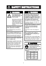
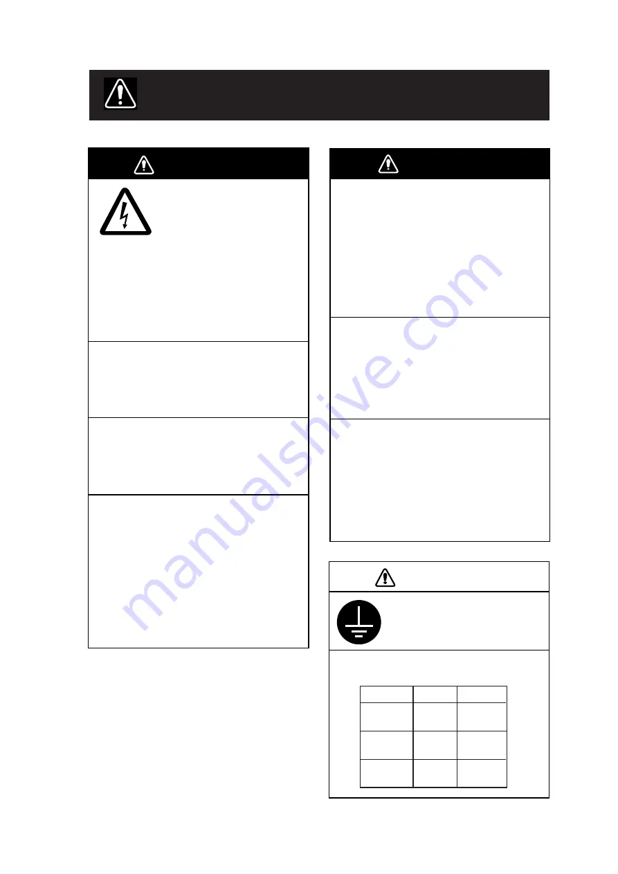
WARNING
Turn off the power at the switchboard
before beginning the installation.
Fire or electrical shock can result if the
power is left on.
Do not install the equipment where it
may get wet from rain or water splash.
Water in the equipment can result in fire,
electrical shock or equipment damage.
Be sure no water leaks in at the trans-
ducer installation site.
Water leakage can sink the vessel. Also
confirm that the transducer will not loosen
by ship’s vibration. The installer of the
equipment is solely responsible for the
proper installation of the equipment.
FURUNO will assume no responsibility for
any damage associated with improper
installation.
Do not open the cover
unless totally familiar with
electrical circuits and
service manual.
High voltage exists inside the
equipment, and a residual
charge remains in capacitors
several minutes after the
power is turned off. Improper
handling can result in electri-
cal shock.
WARNING
Install the specified transducer tank
in accordance with the installation
instructions. If a different tank is to be
installed the shipyard is solely respon-
sible for its installation, and it should
be installed so the hull will not be
damaged if the tank strikes an object.
The tank or hull may be damaged if the
tank strikes an object.
If a steel tank is installed on a wooden
or FRP vessel, take appropriate
measures to prevent electrolytic
corrosion.
Electrolytic corrosion can damage the
hull.
Be sure that the power supply is
compatible with the voltage rating of
the equipment.
Connection of an incorrect power supply
can cause fire or equipment damage. The
voltage rating of the equipment appears
on the label above the power connector.
CAUTION
Observe the following compass safe
distances:
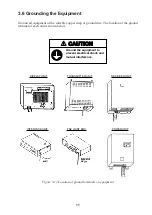
Ground the equipment to
prevent electrical shock and
mutual interference.
Display unit
for CSH-23
Display unit
for CSH-24
Standard Steering
0.9 m 0.68 m
1.70 m 1.30 m
SAFETY INSTRUCTIONS
Processor
unit
1.70 m 1.05 m
Summary of Contents for CSH-23
Page 1: ...COLOR SCANNING SONAR MODEL CSH 23 23F 24 24F Back ...
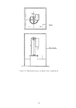
Page 9: ...4 Figure 3 2 Maintenance space example sonar compartment ...
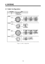
Page 17: ...12 4 WIRING 4 1 Cable Configuration Figure 4 1 Cable configuration ...
Page 53: ...A 4 ...
Page 54: ...A 5 ...
Page 61: ...A 12 ...
Page 71: ...A 22 ...
Page 72: ...A 23 ...
Page 73: ...A 24 ...
Page 74: ...A 25 ...
Page 75: ...A 26 ...
Page 76: ...A 27 ...
Page 77: ...A 28 ...
Page 78: ...A 29 ...
Page 79: ......
Page 80: ...D 2 ...
Page 81: ...Y Hatai D 3 ...
Page 82: ...D 4 ...
Page 83: ...Oct 31 03 D 5 ...
Page 84: ...D 6 ...
Page 85: ...D 7 ...
Page 86: ...D 8 ...
Page 87: ...Dec 10 02 D 9 ...
Page 88: ...D 10 ...
Page 89: ...D 11 ...
Page 90: ...D 12 ...
Page 91: ...D 13 ...
Page 92: ...D 14 ...
Page 93: ...D 15 ...
Page 94: ...D 16 ...
Page 96: ...S 2 ...


