11
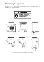
3.6 Grounding the Equipment
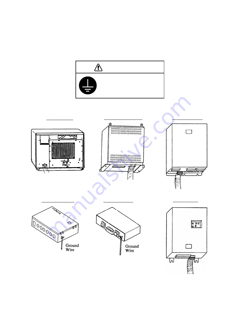
Ground all equipment with a suitable copper strap or ground wire. The location of the ground
terminal of each unit is shown below.
CAUTION
Ground the equipment to
prevent electrical shock and
mutual interference.
DISPLAY UNIT
TRANSMITTER UNIT
RECEIVER UNIT
INTERFACE UNIT
FNZ JOINT BOX
POWER UNIT
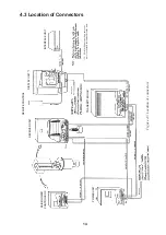
Figure 3-12 Location of ground terminals on equipment
Summary of Contents for CSH-23
Page 1: ...COLOR SCANNING SONAR MODEL CSH 23 23F 24 24F Back ...
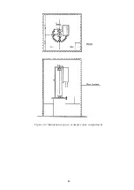
Page 9: ...4 Figure 3 2 Maintenance space example sonar compartment ...
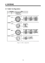
Page 17: ...12 4 WIRING 4 1 Cable Configuration Figure 4 1 Cable configuration ...
Page 53: ...A 4 ...
Page 54: ...A 5 ...
Page 61: ...A 12 ...
Page 71: ...A 22 ...
Page 72: ...A 23 ...
Page 73: ...A 24 ...
Page 74: ...A 25 ...
Page 75: ...A 26 ...
Page 76: ...A 27 ...
Page 77: ...A 28 ...
Page 78: ...A 29 ...
Page 79: ......
Page 80: ...D 2 ...
Page 81: ...Y Hatai D 3 ...
Page 82: ...D 4 ...
Page 83: ...Oct 31 03 D 5 ...
Page 84: ...D 6 ...
Page 85: ...D 7 ...
Page 86: ...D 8 ...
Page 87: ...Dec 10 02 D 9 ...
Page 88: ...D 10 ...
Page 89: ...D 11 ...
Page 90: ...D 12 ...
Page 91: ...D 13 ...
Page 92: ...D 14 ...
Page 93: ...D 15 ...
Page 94: ...D 16 ...
Page 96: ...S 2 ...

