32
4.
9
Interlocking Operation with Other Sonar
Functions (range, tilt, fish mark, etc.) and remote control may be mutually interlocked with
those on other sonars (CSH-23/24/73/83/84). For example, if the range is interlocked, changing
the range in one sonar automatically sets the other sonar to the same range. The functions to be
interlocked can be selected on the SYSTEM menu. See the operator’s manual for further de-
tails.
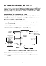
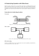
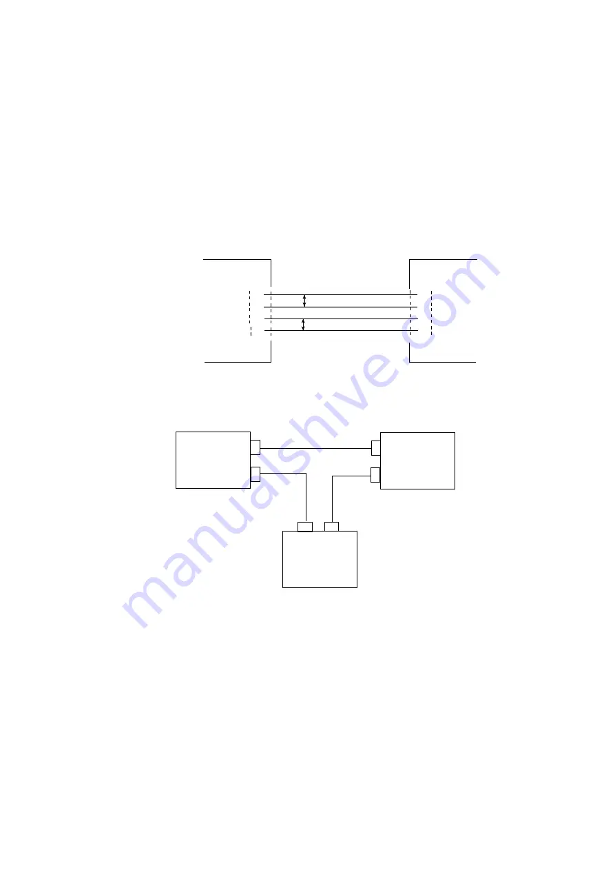
Connections for interlocking functions
Two sonars
Sonar 1
CN-A4
TD H <A<
TD C <B<
RD H <E<
RD C <F<
Sonar 2
CN-A4
>E> RD H
>F> RD C
>A> TD H
>B> TD C
P
P
Figure 4-35 connections for interlocking function of two sonars
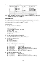
Three sonars
Sonar 1
Sonar 2
TD
RD
RD
TD
TD
RD
Sonar 3
Figure 4-36 Connections for interlocking functions of three sonars
DIP switch setting
Set ID code on DIP switch #1 to #3 on main panel. Any code is acceptable, provided that it is
not the same as that set on the other sonar.
Summary of Contents for CSH-23
Page 1: ...COLOR SCANNING SONAR MODEL CSH 23 23F 24 24F Back ...
Page 9: ...4 Figure 3 2 Maintenance space example sonar compartment ...
Page 17: ...12 4 WIRING 4 1 Cable Configuration Figure 4 1 Cable configuration ...
Page 53: ...A 4 ...
Page 54: ...A 5 ...
Page 61: ...A 12 ...
Page 71: ...A 22 ...
Page 72: ...A 23 ...
Page 73: ...A 24 ...
Page 74: ...A 25 ...
Page 75: ...A 26 ...
Page 76: ...A 27 ...
Page 77: ...A 28 ...
Page 78: ...A 29 ...
Page 79: ......
Page 80: ...D 2 ...
Page 81: ...Y Hatai D 3 ...
Page 82: ...D 4 ...
Page 83: ...Oct 31 03 D 5 ...
Page 84: ...D 6 ...
Page 85: ...D 7 ...
Page 86: ...D 8 ...
Page 87: ...Dec 10 02 D 9 ...
Page 88: ...D 10 ...
Page 89: ...D 11 ...
Page 90: ...D 12 ...
Page 91: ...D 13 ...
Page 92: ...D 14 ...
Page 93: ...D 15 ...
Page 94: ...D 16 ...
Page 96: ...S 2 ...

