8
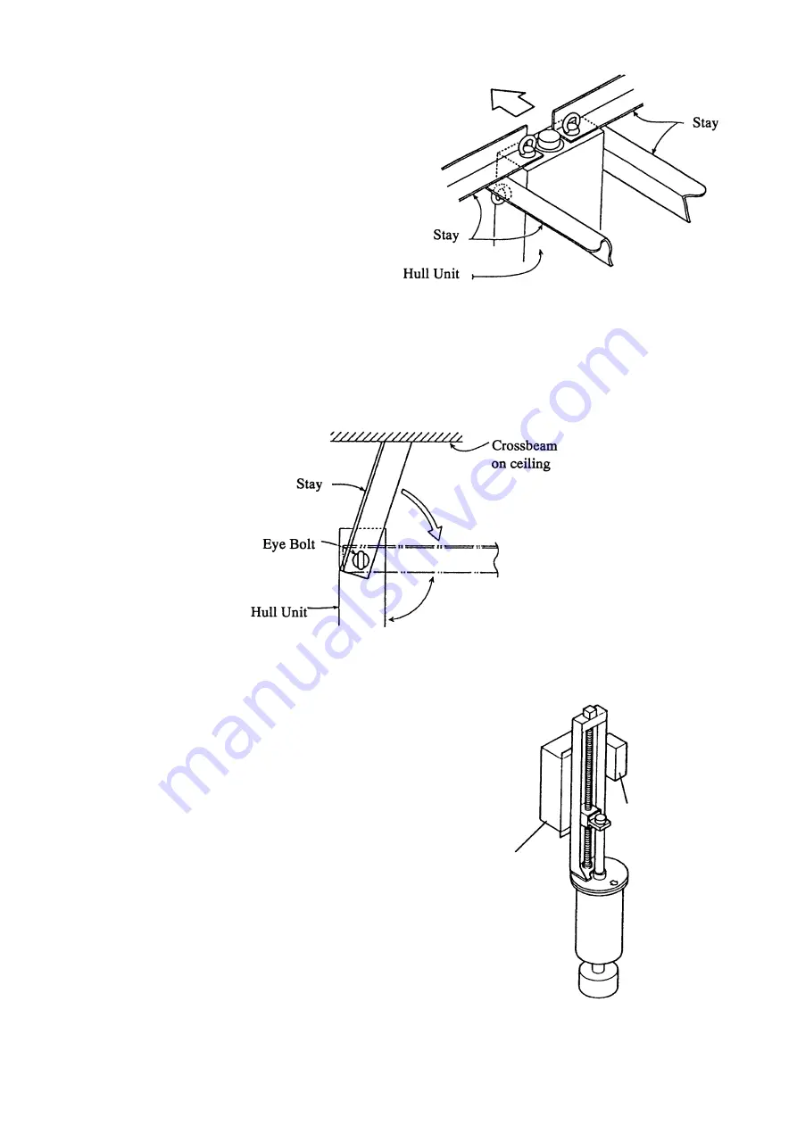
Installing stays (anti-vibration
measure)
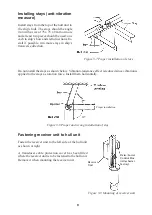
Install stays from the top of the hull unit to
the ship’s hull. The stays should be angle
iron with a size of 75 x 75 x 9 mm or more
and at least two pieces should be used; one
each to ship’s bow and stern directions. In-
stall if possible, two more stays in ship’s
transverse direction.
Do not install the stays as shown below. Vibration-resistance effect is reduced since vibration is
applied to the stays as rotation force. Install them horizontally.
Figure 3-8 Proper and wrong installation of stay
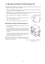
Fastening receiver unit to hull unit
Fasten the receiver unit to the left side of the hull unit
as shown at right.
A transducer cable protection cover has been fitted
where the receiver unit is to be fastened to the hull unit.
Remove it when mounting the receiver unit.
Raise/Lower
Control Box
(Attached at
factory)
Receiver
Unit
Figure 3-7 Proper installation of stays
90
°
Proper installation
Figure 3-9 Mounting of receiver unit
Summary of Contents for CSH-23
Page 1: ...COLOR SCANNING SONAR MODEL CSH 23 23F 24 24F Back ...
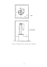
Page 9: ...4 Figure 3 2 Maintenance space example sonar compartment ...
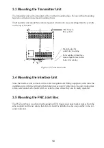
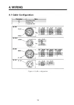
Page 17: ...12 4 WIRING 4 1 Cable Configuration Figure 4 1 Cable configuration ...
Page 53: ...A 4 ...
Page 54: ...A 5 ...
Page 61: ...A 12 ...
Page 71: ...A 22 ...
Page 72: ...A 23 ...
Page 73: ...A 24 ...
Page 74: ...A 25 ...
Page 75: ...A 26 ...
Page 76: ...A 27 ...
Page 77: ...A 28 ...
Page 78: ...A 29 ...
Page 79: ......
Page 80: ...D 2 ...
Page 81: ...Y Hatai D 3 ...
Page 82: ...D 4 ...
Page 83: ...Oct 31 03 D 5 ...
Page 84: ...D 6 ...
Page 85: ...D 7 ...
Page 86: ...D 8 ...
Page 87: ...Dec 10 02 D 9 ...
Page 88: ...D 10 ...
Page 89: ...D 11 ...
Page 90: ...D 12 ...
Page 91: ...D 13 ...
Page 92: ...D 14 ...
Page 93: ...D 15 ...
Page 94: ...D 16 ...
Page 96: ...S 2 ...


