23
4.5 Connection of Transducer Cables
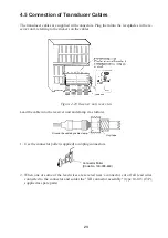
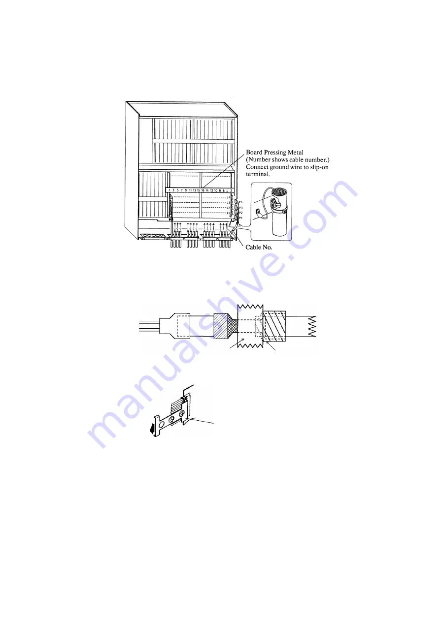
The transducer cables are supplied with connectors. Plug them into the receptacles in the re-
ceiver unit, referring to the stickers on the cables.
Figure 4-23 Receiver unit, rear view
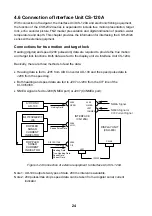
Lead the cable into the receiver unit and clamp it as follows.
Vinyl tape
Ground the cable by cable clamp.
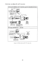
1. Use the connector puller (supplied) to unplug connectors.
Connector Puller
(Code No. 100-008-460)
2. When one or some of the lead wires are severed near a connector, cut off all lead wires
connected to the connector and solder the "XH connector assembly" (type 10-145 (13P),
supplied as spare parts).
Summary of Contents for CSH-23
Page 1: ...COLOR SCANNING SONAR MODEL CSH 23 23F 24 24F Back ...
Page 9: ...4 Figure 3 2 Maintenance space example sonar compartment ...
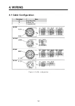
Page 17: ...12 4 WIRING 4 1 Cable Configuration Figure 4 1 Cable configuration ...
Page 53: ...A 4 ...
Page 54: ...A 5 ...
Page 61: ...A 12 ...
Page 71: ...A 22 ...
Page 72: ...A 23 ...
Page 73: ...A 24 ...
Page 74: ...A 25 ...
Page 75: ...A 26 ...
Page 76: ...A 27 ...
Page 77: ...A 28 ...
Page 78: ...A 29 ...
Page 79: ......
Page 80: ...D 2 ...
Page 81: ...Y Hatai D 3 ...
Page 82: ...D 4 ...
Page 83: ...Oct 31 03 D 5 ...
Page 84: ...D 6 ...
Page 85: ...D 7 ...
Page 86: ...D 8 ...
Page 87: ...Dec 10 02 D 9 ...
Page 88: ...D 10 ...
Page 89: ...D 11 ...
Page 90: ...D 12 ...
Page 91: ...D 13 ...
Page 92: ...D 14 ...
Page 93: ...D 15 ...
Page 94: ...D 16 ...
Page 96: ...S 2 ...

