


4-3
< Tuning procedure >
1) Preparation
Check the rating plate on the motor and set the following function codes to their nominal
ratings:
• F04 and A02: Base frequency
• F05 and A03: Rated voltage at base frequency
• P02 and A16: Motor rated capacity
• P03 and A17: Motor rated current
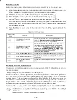
2) Selection of tuning process
Check the situation of the machine system and select either "Tuning while the motor is
stopped (P04 or A18 = 1)" or "Tuning while the motor is running (P04 or A18 = 2)." In the
case of "Tuning while the motor is running (P04 or A18 = 2)," also adjust the acceleration
and deceleration times (F07 and F08) and set the rotation direction properly so that it
matches the actual rotation direction of the machine system.
Data for
P04, A18
Motor parameters
subjected to tuning:
Tuning type
Selection condition
of tuning type
1
Primary resistance
(%R1) (P07, A21)
Leakage reactance
(%X) (P08, A22)
Tuning the %R1 and %X,
with the motor being
stopped.
The motor cannot be rotated
or 50% or more of the rated
load would be applied to the
motor if rotated.
2
Primary resistance
(%R1) (P07, A21)
Leakage reactance
(%X) (P08, A22)
No-load current
(P06, A20)
Rated slip frequency
(P12, A26)
Tuning the %R1 and %X,
with the motor being
stopped.
Tuning the no-load current,
with the motor running at
50% of the base frequency.
Even if the motor is rotated, it
is safe and no more than 50%
of the rated load would be
applied to the motor if rotated.
(Tuning with no load will
obtain the highest precision.)
Upon completion of the tuning, each motor parameter will be automatically saved into the
applicable function code.
3) Preparation of machine system
Perform appropriate preparations on the motor and its load, such as disengaging the
coupling and deactivating the safety device.
Switch to the motor 1 or motor 2, which the tuning is to be performed on.
Tuning results by P04 will be applied to P codes for the motor 1, and tuning results by A18
will be applied to A codes for the motor 2.
Assigning the
SWM2
signal ("Switch to motor 2")
to terminal [Y1] or [30A/B/C]
automatically switches the output status of
SWM2
depending on the motor
selected for tuning.


