


5-5
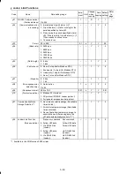
(F codes continued)
Code
Name
Data setting range
Incre-
ment
Unit
Change
when
running
Data
copying
Default
setting
Refer
to
page:
F42
Control Mode Selection
1
0: V/f control with slip compensation
inactive
–
–
N
Y
0
5-41
1: Dynamic torque vector control
2: V/f control with slip compensation active
11: V/f control for PMSM drive *1
F43
Current Limiter
0:
Disable (No current limiter works.)
–
–
Y
Y
2
5-42
(Mode selection) 1:
Enable at constant speed (Disable
during ACC/DEC)
2:
Enable during ACC/constant speed
operation
F44
(Level) 20 to 180:3.7kW or below
20 to 200:5.57kW or above
(The data is interpreted as the rated output
current of the inverter for 100%) *3
1
%
Y
Y
160
or
180
*6
F50
Electronic Thermal
Overload Protection for
Braking Resistor
1 to 900, OFF (Cancel)
1
kWs
Y
Y1
Y2
OFF
(Discharging capability)
F51
(Allowable average loss) 0.001 to 50.00
0.001 kW
Y
Y1
Y2
0.001
*1 Available in the ROM version 0500 or later.
*3
For the single-phase 100 V class series, the percentage is relative to the reference current; for other series, it is relative to the rated output current.
*6 160 for inverter of 3.7 kW (5HP) or below; 180 for those of 5.5 kW (7.5HP) or above.


