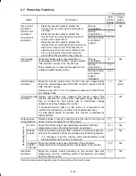
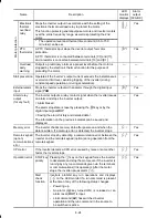


11-4
3) Use shielded wires for the control signals of the inverter to input to or output from the control
terminals. Firmly clamp the control wire shields to the EMC grounding flange (in the same way
as the motor cables).
Figure 11.2 Connecting Shielded Cables
4) If noise from the inverter exceeds the permissible level, enclose the inverter and its peripherals
within a metal panel as shown in Figure 11.3.
Figure 11.3 Installing the Inverter into a Metal Panel
■
In the case an outboard, EMC-compliant (optional) is used
1) Install the inverter and the filter on a grounded metal plate. Use a shielded cable also for
connection of the motor. Make the motor cable as short as possible. Connect the shielding
layer firmly to the metal plate. Also connect the shielding layer electrically to the grounding
terminal of the motor.
2) Use shielded cable for connection around the control terminals of the inverter and also for
connection of the RS-485 signal cable. As with the motor, clamp the shielding layer firmly to a
grounded plate.
3) If noise from the inverter exceeds the permissible level, enclose the inverter and its peripherals
within a metal panel as shown in Figure 11.4.


