


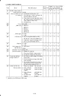


5-16
A codes: Motor 2 Parameters
Code
Name
Data setting range
Incre-
ment
Unit
Change
when
running
Data
copying
Default
setting
Refer
to
page:
A01
Maximum Frequency 2
25.0 to 400.0
0.1
Hz
N
Y
ACU
:60.0
E:50.0
–
A02
Base Frequency 2
25.0 to 400.0
0.1
Hz
N
Y
AU:60.0
CE:50.0
A03
Rated Voltage at Base
Frequency 2
0: Output a voltage in proportion to input
voltage
80 to 240V: Output an AVR-controlled
voltage (Note 1)
1
V
N
Y2
ACE:0
U:230/
460
160 to 500V: Output an AVR-controlled
voltage (Note 2)
A04
Maximum Output
Voltage 2
80 to 240V: Output an AVR-controlled
voltage (Note 1)
160 to 500V: Output an AVR-controlled
voltage (Note 2)
1
V
N
Y2
A: 220/
380
C: 200
380
E: 230/
400
U: 230/
460
A05
Torque Boost 2
0.0% to 20.0%
(percentage with respect to "A03: Rated
Voltage at Base Frequency 2")
0.1
%
Y
Y
See
Table
A.
A06
Electronic Thermal
Overload Protection for
Motor 2
(Motor characteristics)
1: For a general-purpose motor with
shaft-driven cooling fan
–
–
Y
Y
1
2: For an inverter-driven motor with
separately powered cooling fan
A07
(Overload detection
level)
0.00 (Disable), 0.01 to 100.0
1 to 135% of the rated current (allowable
continuous drive current) of the motor
0.01
A
Y
Y1
Y2
See
Table
A.
A08
(Thermal time constant) 0.5 to 75.0
0.1
min
Y
Y
5.0
A09
DC Braking 2
0.0 to 60.0
0.1
Hz
Y
Y
0.0
(Braking starting
frequency)
A10
(Braking level) 0 to 100 *3
1
%
Y
Y
0
A11
(Braking time) 0.00 : Disable
0.01 to 30.00
0.01
s
Y
Y
0.00
A12
Starting Frequency 2
0.1 to 60.0
0.1
Hz
Y
Y
1.0
A13
Load Selection/
Auto Torque Boost/
Auto Energy Saving
Operation 2
0: Variable torque load
–
–
N
Y
1
1: Constant torque load
2: Auto-torque boost
3: Auto-energy saving operation (Variable
torque load during ACC/DEC)
4: Auto-energy saving operation (Constant
torque load during ACC/DEC)
5: Auto-energy saving operation
(Auto-torque boost during ACC/DEC)
A14
Control Mode Selection
2
0: V/f control with slip compensation
inactive
–
–
N
Y
0
1: Dynamic torque vector control
2: V/f control with slip compensation active
A16
Motor 2 (Rated capacity) 0.01 to 30.00 (kW when A39 = 0, 3, or 4)
0.01 to 30.00 (HP when A39 = 1)
0.01
0.01
kW
HP
N
Y1
Y2
See
Table
A.
(Note) Alphabets in the Default setting field denote shipping destination: A (Asia), C (China), E (Europe) and U (USA).
*3 For the single-phase 100 V class series, the percentage is relative to the reference current; for other series, it is relative to the rated output current.
(Note 1)
For the three-phase / single-phase 200 V and single-phase 100 V class series
(Note 2)
For the three-phase 400 V class series


