


6-8
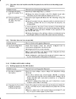
[ 7 ] The motor does not restart even after the power recovers from a momentary power
failure.
Possible Causes
What to Check and Suggested Measures
(1) The data of function
code F14 is either "0" or
"1."
Check if an undervoltage trip (
lu
) occurs.
Change the data of function code F14 (Restart mode after
momentary power failure (Mode selection)) to "4" or "5."
(2) The run command
remains OFF even after
the power has been
restored.
Check the input signal with Menu #4 "I/O Checking" using the
keypad.
Check the power recovery sequence with an external circuit. If
necessary, consider the use of a relay that can keep the run
command ON.
In 3-wire operation, the power to the inverter's control PCB has
been shut down once because of a long momentary power failure,
or, the
HLD
terminal command ("Enable 3-wire operation") has
been turned OFF once.
Change the design or the setting so that a run command can be
issued again within 2 seconds after power has been restored.
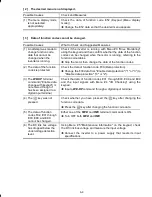
[ 8 ] The motor does not run as expected.
Possible Causes
What to Check and Suggested Measures
(1) Incorrect configuration
of function codes
Check that function codes are correctly configured and no
unnecessary configuration has been made.
Configure all function codes correctly.
Make a note of function code data currently configured and then
initialize all function code data (H03).
After initialization, reconfigure the necessary function codes one
by one, checking the running status of the motor.
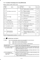
6.2.2 Problems with inverter settings
[ 1 ] Nothing appears on the LED monitor.
Possible Causes
What to Check and Suggested Measures
(1) No power supplied to
the inverter.
Check the input voltage, output voltage and interphase voltage
unbalance.
Turn ON a molded case circuit breaker (MCCB), a residual-
current-operated protective device (RCD)/earth leakage circuit
breaker (ELCB) (with overcurrent protection) or a magnetic
contactor (MC).
Check for voltage drop, phase loss, poor connections, or poor
contacts, and fix them if necessary.
(2) The power for the control
PCB did not reach a
sufficiently high level.
Check if the jumper bar has been removed between terminals P1
and P(+) or if there is poor contact between the jumper bar and the
terminals.
Mount a jumper bar or DC reactor between terminals P1 and
P(+). For poor contact, tighten up the screws.


