background image


CONTACT INFORMATION 


Fuji Electric Europe Headquarters 

Fuji Electric Europe GmbH 

Goethering 58 
63067 Offenbach am Main 
Germany 
Tel.: +49 69 669029 0  
Fax: +49 69 669029 59 
[email protected] 
www.fujielectric-europe.com 


Switzerland 

Fuji Electric Europe GmbH, Swiss Branch 

Rietlistrasse 5 
9403 Goldach 
Tel.: +41 (0) 71 858 29 49 
Fax: +41 (0) 71 858 29 40 
[email protected] 
www.fujielectric-europe.com 


France


Fuji Electric Europe GmbH, Succursale France 

265 Rue Denis Papin 
38090 Villefontaine 
Tel.: +33 4 74 90 91 24 
Fax: +33 4 74 90 91 75 
[email protected] 
www.fujielectric-europe.com 


United Kingdom 

Fuji Electric Europe GmbH, UK Branch


Bedford i-Lab 
Stannard Way 
Priory Business Park 
Bedford MK44 3RZ 
Tel.: +44 (0) 1234 834 768 
[email protected] 
www.fujielectric-europe.com 


Spain 

Fuji Electric Europe GmbH, Sucursal en España 

Carrer dels paletes 8, Edifici B, Planta 1, Oficina B 
Parc Tecnològic del Vallès 
08290 Cerdanyola del Vallès (Barcelona)  
Tel.: +34 935 824 333 
Fax: +34 935 824 344 
[email protected] 
www.fujielectric-europe.com 


Italy 

Fuji Electric Europe GmbH, Filiale Italiana


Via Rizzotto 46 
41126 Modena (MO) 
Tel.: +39 059 4734 266  
Fax: +39 059 4734 294 
[email protected] 
www.fujielectric-europe.com 


Subject to change without prior notice


Summary of Contents for FRENIC-Lift FRN0010WLM2A-4E

Page 1: ...hree phase permanent magnet synchronous motors Read through this manual to become familiar with the handling procedure and correct use Improper handling might result in incorrect operation short life...

Page 2: ...nted Solution Page 2 of 20 Fuji Electric Europe GmbH Version Changes applied Date Written Checked Approved 1 0 0 First release 11 11 2020 C Arjona J Alonso J Catal 1 0 1 Small text corrections xx 11 2...

Page 3: ...erminals 13 2 4 1 Removing the front cover of the Wall Mounted 13 2 4 2 Mounting the front cover 13 2 4 3 Recommended wire sizes 13 2 4 4 Terminal arrangement diagrams and screw specifications 14 2 4...

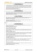
Page 4: ...Be sure to obtain the latest editions for use Safety precautions Read this manual thoroughly before proceeding with installation connections wiring operation or maintenance and inspection Ensure you h...

Page 5: ...e to ground the inverter s grounding terminals G Otherwise an electric shock or a fire could occur Qualified electricians should carry out wiring Be sure to perform wiring after turning the power OFF...

Page 6: ...over of the inverter before turning the power ON Do not remove the cover when the inverter power is ON Otherwise an electric shock could occur Do not operate switches with wet hands Doing so could cau...

Page 7: ...carrying out regular inspections could result in malfunction or damage and an accident or fire could occur It is recommended that periodic inspections be carryout every one to two years however they...

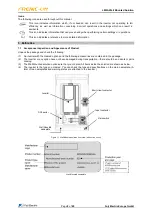
Page 8: ...ppearance of Product Unpack the package and check the following 1 An inverter with the ordered options and the following accessories are contained in the package 2 The inverter or any option have not...

Page 9: ...with non flammable material Do not mount the cabinet upside down or horizontally 2 Clearances Ensure that the minimum clearances indicated in Figure 2 1 and Table 2 1 are maintained at all times By en...

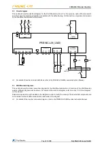
Page 10: ...KSC KIN 1 2 3 4 X1 220 VAC Control Terminals Control Terminals A1 A1 A2 A2 For details of inverter terminal definitions refer to the FRENIC Lift LM2A series Instruction Manual 2 3 Wall Mounted diagram...

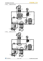
Page 11: ...3 MCCB or RCD ELCB 2 Common Terminals 1 2 3 4 Main Switch 220 VAC 7 Y3C SCC 1 L1 3 L2 5 L3 2 T1 4 T2 6 T3 11 11 1 KIN A2 A2 A1 4 2 KSC A2 KIN A1 R1 R2 R3 R4 14 13 A1 A2 FRN_ _ _ _WLM2A 4E OPT S1 FRENI...

Page 12: ...1 5 4 9 9 9 9 Braking Resistor 6 L1 R L2 S L3 T Input KIN Fuse 3 MCCB or RCD ELCB 2 Common Terminals 1 2 3 4 Main Switch 220 VAC 7 1 L1 3 L2 5 L3 2 T1 4 T2 6 T3 1 KIN A2 A2 A1 4 KIN A1 FRN_ _ _ _WLM2...

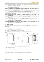
Page 13: ...Note 8 Jumper to connect disconnect internal EMC filter It is a metal plate placed on the EMC terminal Note 9 Removable terminals For detailed information refer to FRENIC Lift LM2A series Instruction...

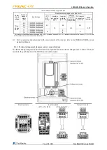
Page 14: ...25WLM2A 4E 6 4 6 15 FRN0032WLM2A 4E 6 Terminals for Wall Mounted solution option N3 or S3 In case of options N1 or S1 terminal are located in the inverter L1 R L2 S and L3 T with the same wire size de...

Page 15: ...ter output for Short circuit U0 V0 W0 For a short circuit for PMS motor These outputs are connected internally to U V W DC reactor connection terminals P2 P3 Terminals for built in DC Reactor connecti...

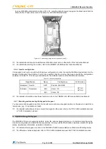
Page 16: ...ration Classification Name Configuration WM Version Hardware Switch SW1 Position SOURCE OPT S1 OPT S3 Software Parameter E04 Value 115 E22 Value 123 For detailed information about these functions refe...

Page 17: ...foreign or dangerous objects are left Input voltage Check that the input voltages of the main and control circuit are correct Measure the input voltages using a multimeter or the like The standard sp...

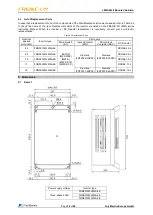
Page 18: ...lt your Fuji Electric representative Table 4 2 Replacement Parts Nominal applied motor kW Inverter type Part name Main Switch S1 Input Contactor KIN Short circuit Contactor KSC DC Reactor 4 0 FRN0010W...

Page 19: ...LM2A Wall Mounted Solution Page 19 of 20 Fuji Electric Europe GmbH 5 2 Frame 2 Power supply voltage Inverter type Three phase 400V FRN0025WLM2A 4E FRN0032WLM2A 4E...

Page 20: ...nfo france fujielectric europe com www fujielectric europe com United Kingdom Fuji Electric Europe GmbH UK Branch Bedford i Lab Stannard Way Priory Business Park Bedford MK44 3RZ Tel 44 0 1234 834 768...

Reviews: