LM2A Wall Mounted Solution
Page
15
of
20
Fuji Electric Europe GmbH
Table 2.3 Terminal Characteristics
Terminal block
type
Screw
specifications
Recommended wire
size (mm
2
)
Type of screwdriver (tip shape)
Wire strip length
Block terminals
Screwless
0.5 to 2.5 mm
2
(AWG20 to 14)
Flat screwdriver (0.5 mm x 3.0 mm)
6 mm
Input contactor
Screwless
1 to 10 mm
2
(AWG18 to 8)
Flat screwdriver (0.5 mm x 3.0 mm)
10 mm
2.4.5 Terminal functions
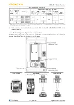
The table below shows the main terminal functions. Differences between Wall Mounted versions are noted on each
description.
Table 2.4 Functions of Main Circuit Terminals
Classifi-
cation
Name
Symbol
Functions
Inverter
Primary grounding
terminals for inverter
enclosure
G
The two grounding terminals ( G) can be either used for the power supply
wiring (primary circuit) or motor wiring (secondary circuit). Be sure to
ground either of the two grounding terminals for safety and noise reduction.
Inverter output
terminals
U, V, W
Connect the three wires of the 3-phase motor to terminals U, V, and W,
taking care of the correct motor phase correspondence.
Inverter output for
Short circuit
U0, V0, W0
For a short circuit for PMS motor.
These outputs are connected internally to U, V, W.
DC reactor
connection terminals
P2, P3
Terminals for built-in DC Reactor connection. Do not unwire them. If for
any reason DCR is removed, make a bridge between these terminals.
Main circuit power
input terminals
L1/R, L2/S,
L3/T
The three-phase input power lines are connected to these terminals.
Only for option
s “S1” and “N1”.
WM
terminals
Input contactor
1/L1, 3/L2,
5/L3
Wired from factory to main circuit power input terminals on the inverter
(L1/R, L2/S, L3/T). Do not remove the factory wiring.
2/T1, 4/T2,
6/T3
The three-phase input power lines are connected to these terminals.
Only for opt
ions “S3” and “N3”.
Block terminals
[1], [2]
Input power supply for contactors coils, 230 VAC.
Do not remove the factory wiring.
[3], [4]
Do not remove the factory wiring.
Do not remove the jumper between terminals 2 and 3.
Wiring notes
To make the machinery or equipment compliant with the EMC standards, wire the motor and inverter in accordance
with the following.
Use shielded wires for the motor cable and route the cable as short as possible. Firmly clamp the shield to the
grounded metal plate.
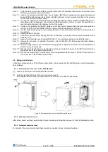
Figure 2.3 Connection method with shield plate of input and output terminals
Tight wire


