


LM2A Wall Mounted Solution
Page
10
of
20
Fuji Electric Europe GmbH
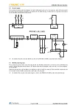
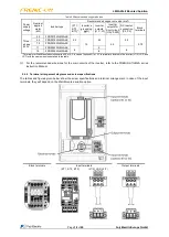
2.2 Circuit diagram
This section shows the electrical diagram for the Wall Mounted solution. For this purpose, option S3 (main switch
and short-circuit contactor by default) is presented with the default wiring. On this section, only elements included
on the Wall Mounted solution will be drawn.
FRENIC-Lift (LM2)
DC Reactor
U
V
W
MOTOR
G
P2
N(-)
DB
P3
P(+)
G
W0
V0
U0
L1/R L2/S L3/T
Input
-KIN
1/L1 3/L2 5/L3
2/T1 4/T2 6/T3
PLC
-KSC
R1
R2
R3
R4
14
13
-KSC
X4
11
12
-S1
Y3C
Y3A
-KSC
-KIN
1
2
3
4
-X1
220 VAC
Control
Terminals
Control
Terminals
A1
A1
A2
A2
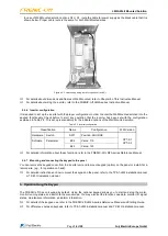
For details of inverter terminal definitions, refer to the FRENIC-Lift LM2A series Instruction Manual.
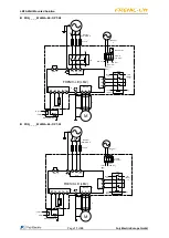
2.3 Wall Mounted diagrams
This section shows the main connection diagram for the Wall Mounted solution. In function of the Wall Mounted
version, different diagrams will be shown. For details of the electrical diagram, refer to section
“2.2 Circuit diagram”
on this manual.
External components could be added to the diagram in order to clarify the concept. These external components are
not included into the Wall Mounted solution and noted in the diagram.
For details of the inverter connection diagram, refer to the FRENIC-Lift LM2A series Instruction Manual.