LM2A Wall Mounted Solution
Page
9
of
20
Fuji Electric Europe GmbH
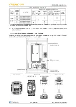
* Depending on Inverter ROM version and capacity. For additional information, check FRENIC-Lift LM2A series Starting Guide.
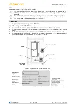
Figure 1.2 How to read Wall Mounted solution type name
If you suspect the product is not working properly or if you have any questions about your product, contact your Fuji
Electric representative.
1.2 Usage and Storage environment
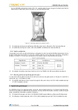
For details of the usage environment and storage environment, refer to the FRENIC-Lift LM2A series Instruction
Manual.
2. Mounting and Wiring the Wall Mounted
2.1 Installing the cabinet
(1) Mounting base
Make sure to install Wall Mounted solution in a surface able to support its load and
with non-flammable material. Do not mount the cabinet upside down or horizontally.
(2) Clearances
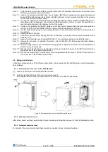
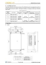
Ensure that the minimum clearances indicated in Figure 2.1 and Table 2.1 are
maintained at all times. By ensuring the clearance distances, a good ventilation
inside the cabinet is ensured. Bad ventilation can lead the temperature rise and the
malfunction of some components.
When mounting two or more cabinets
When mounting two or more cabinets in the same unit, basically lay them out side
by side. When mounting them one above the other, be sure to separate them with
a partition plate or the like so that any heat radiating from one cabinet will not affect
the one(s) above.
Table 2.1 Clearances
mm (inch)
Inverter capacity
A
B
C
D *1
400V class series:
FRN0010WLM2A-4E
to
0
10
100
0
FRN0032WLM2A-4E
(0)
(0.39)
(3.9)
(0)
*1) D: Space required in front of the inverter unit
Figure 2.1 Mounting Direction and
Required Clearances


