LM2A Wall Mounted Solution
Page
16
of
20
Fuji Electric Europe GmbH
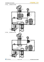
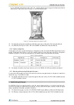
In case of Wall Mounted solution options N1 or S1, route the cable for power supply as the black cable that it is
shown below. Proper cable route is the same for both Wall Mounted sizes.
Figure 2.4. Power supply wiring route for options N1 and S1.
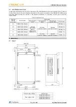
For details about dimensions and frames of Wall Mounted, refer to Chapter 5 of this Instruction Manual.
For details about wiring the inverter, refer to the FRENIC-Lift LM2A series Instruction Manual.
2.4.6 Inverter configuration
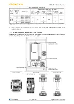
It is required to set up the inverter with the proper configuration in order to enter the Wall Mounted solution into the
desired functionality. Check before to start any operation that the inverter has been set with the configuration
explained in Table 2.5. This set up is mandatory for the indicated options of the Wall Mounted solution.
Table 2.5. Inverter configuration.
Classification
Name
Configuration
WM Version
Hardware
Switch
SW1
Position: SOURCE
OPT-S1
OPT-S3
Software
Parameter
E04
Value: 115
E22
Value: 123
For detailed information about these functions, refer to the FRENIC-Lift LM2A series Reference Manual.
2.4.7 Mounting and connecting the keypad to the panel
You can remove the keypad cover from the inverter unit and to mount keypad (option) on the panel or install it at a
remote site. (e.g., for operation on hand).
For detailed instructions on how to mount the keypad on the panel, refer to the TP-A1-LM2 installation manual
or TP-E1U installation manual.
3. Operation Using the Keypad
The FRENIC-Lift has no keypad by default. Using the optional keypad allows you to start and stop the motor,
monitor running status, and switch to the menu mode. You may also set the function code data, monitor I/O signal
states, maintenance information, and alarm information.
For details of the keypad use, refer to the FRENIC-Lift LM2A series Reference Manual and Starting Guide.
For differences between keypads, refer to TP-A1-LM2 installation manual and TP-E1U installation manual.

