background image

5

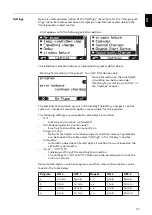
2.5 min

7.5 min

1 x

2.5 min

7.5 min

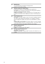
In each of these programs, the solenoid valve opens for a time "ON 1" and closes
for a time "OFF 1". This process is repeated for the number of times specified
under "Repeat". After this number of repetitions has been completed, the pro-
cess continues with the "ON 2" and "OFF 2" times until charging is completed.

Temperature-controlled charging:


The following settings are available for temperature-controlled charging:

-

automatic/OFF/required:

-

automatic ... Temperature-dependent adjustment of the charging char-
acteristic

-

OFF ... The measured battery temperature is not taken into account

-

required ...
Charging only starts when a temperature sensor is connected

-

Error overtemperature ON/OFF:

-

ON ... Error message in the event of battery overtemperature
Charging process stops and can only be continued once the battery has
cooled down and been reconnected

-

OFF ... No error message in the event of battery overtemperature

-

Warning overtemperature ON/OFF:

-

ON ... Warning in the event of battery overtemperature

-

OFF ... No battery overtemperature warning

Equalising charge:

-

OFF:
There is no equalising charge.

-

Delay:
If the battery remains connected to the battery charger for the duration of
the equalising charge delay ("equalize charge delay"), then a special type of
charging takes place. This prevents acid stratification.
The parameters for the current (ampere / 100 ampere hours), voltage (volt /
cell) and duration of the equalising charge can be changed.

-

Weekday:
Specify the weekday on which the equalising charge is to take place.
The parameters for the current (ampere / 100 ampere hours), voltage (volt /
cell) and duration of the equalising charge can be changed.

-

Manual equalising charge ("Manual"):
An equalising charge can be started manually by pressing the relevant key on
the display. The equalising charge starts after a set delay time has been ob-
served. The charge parameters that have been set are followed. The para-
meters for the current (ampere / 100 ampere hours), voltage (volt / cell) and
duration of the equalising charge may all be changed. This function is only
available for Pb-Wet characteristics.

If a setting for the equalising charge is enabled, a symbol on the home screen
next to the set ampere hours or charging time shows whether an equalising
charge is being carried out or can be started.

38

Summary of Contents for Selectiva 2060

Page 1: ...Operating Instructions Selectiva 2040 2kW 2050 2kW 2060 2kW 2070 2kW 2080 3kW 2100 3kW 2120 3kW 4020 2kW 4035 2kW 4045 3kW 4060 3kW 42 0426 0226 EN 011 31052022 EN Operating Instructions ...

Page 2: ......

Page 3: ...tion 12 Charging lead 12 Correct installation of the mains charging cables 12 Warning notices on the device 13 Warning notices inside the device 14 Setup regulations 15 Wall and floor bracket 16 Control elements and connections 21 General 21 Controls and connections 21 Control panel 23 Charging the battery 25 Charging 25 Interrupting charging 27 Stopping charging 28 Display 29 Overview of display ...

Page 4: ...Option box 56 Mounting plate 57 Technical data 58 Selectiva 2 kW 58 Selectiva 3 kW 59 4 ...

Page 5: ...headed General information in the Operating Instructions for your device Before switching on the device rectify any faults that could compromise safety This is for your personal safety Intended use The device is to be used exclusively for its intended purpose Any use above and beyond this purpose is deemed improper The manufacturer is not liable for any damage or unexpected or incorrect results ar...

Page 6: ...dequately di mensioned Loose connections scorched damaged or inadequately dimensioned cables and leads must be immediately repaired by authorised personnel Danger due to acid gases and vapours Batteries contain acid which is harmful to the eyes and skin During charging gases and vapours are released that may be harmful to health and are highly ex plosive in certain circumstances Only use the charg...

Page 7: ...nly be operated on a mains supply with a ground conductor and a socket with a ground conductor contact If the charger is operated on a mains supply without a ground conductor or in a socket without a ground conductor contact this will be deemed gross negligence The manufac turer shall not be held liable for any damage arising from such usage Only operate the charger in accordance with the degree o...

Page 8: ...have been instructed in how to use the device have read and understood these operating instructions especially the sec tion safety rules and have confirmed as much with their signatures are trained to produce the required results Checks must be carried out at regular intervals to ensure that operators are working in a safety conscious manner Safety inspec tion The manufacturer recommends that a sa...

Page 9: ... to adverse health and or environmental impacts Packaging materials Separate collection according to material Check your local authority regulations Crush containers to reduce size Copyright Copyright of these operating instructions remains with the manufacturer The text and illustrations are all technically correct at the time of printing We reserve the right to make changes The contents of the o...

Page 10: ...the requirements of the battery and only charges the battery with the current that it actually needs The technology is embedded in a robust industry standard housing The excep tionally compact design complies with all safety standards requires less installa tion space and protects the components to ensure a long service life Fitted with a graphical display an integrated datalogger new interfaces a...

Page 11: ... 10 700 Selectiva 2080 3 kW Pb Wet GEL 1 12 20 1600 NiCd 2 20 20 1600 Selectiva 2100 3 kW Pb Wet GEL 1 12 20 2000 NiCd 2 20 20 2000 Selectiva 2120 3 kW Pb Wet GEL 1 12 20 2000 NiCd 2 20 20 2000 Selectiva 4045 3 kW Pb Wet GEL 1 24 20 900 NiCd 2 40 20 900 Selectiva 4060 3 kW Pb Wet GEL 1 24 20 1000 NiCd 2 40 20 1000 Any use above and beyond this purpose is deemed improper The manufacturer shall not ...

Page 12: ...charging process This may result in serious injury and damage to property The sparks caused by this can ignite the charging gases that build up during the charging process causing a fire or an explosion Once the charging process is complete wind up the charging leads or if available place them on the cable holder Correct installa tion of the mains charging cables CAUTION Danger due to overheating ...

Page 13: ...n und Funken vermeiden Während des Ladens für ausreichend Frischluft Zufuhr sorgen Always stop charging before you disconnect the charging cable Explosive gases Prevent flames and sparks Provide adequate ventilation during charge Toujours arrêter la charge avant de déconnecter le câble de charge Gaz explosifs Éviter les flammes et les étincelles Prévoir une ventilation adaptée pendant la charge De...

Page 14: ... you disconnect the charging cable OVC II UAC nom IAC max PAC max UDC nom IDC max Part No Ser No Protective class I IP21 1 NPE 230V 50 60Hz xxA xxV xxxxW xxA www fronius com Do not dispose of used devices with domestic waste Dispose of them according to the safety rules Possible sources of ignition such as fire sparks and naked flames must be kept away from the battery Risk of explosion Oxyhydroge...

Page 15: ... GND 14 Status 4 2 Ext Start Stopp Temperature controlled charging WARNING Hazardous Voltage Kondensator Entladezeit 2 min Capacitor discharge time 2 min Décharge de condensateur 2 min Condensador tiempo de descarga 2 min Condensatore tempo di scaricamento 2 min Setup regula tions WARNING Danger from machines falling or toppling over This can result in serious injury and damage to property Make su...

Page 16: ...rtially or fully covered air inlets and outlets This can result in damage to property If several chargers are set up one behind the other they should be offset a If the chargers are arranged in a line one behind the other without being offset the space between the chargers must be as follows a Minimum distance 20 cm 7 87 in Wall and floor bracket WARNING Danger due to work that has been carried ou...

Page 17: ... screw connections are secure Use only with the battery charger provided by the manufacturer Ensure the device is level when mounting If the device is mounted on the wall ensure the wall is capable of supporting the weight of the device Weight of wall bracket 2 kW B1 1 10 kg 2 43 lb 3 kW C1 1 35 kg 2 98 lb 1 TX25 3 3 3 2 17 EN ...

Page 18: ...2 kW B1 mm in 341 13 43 182 7 17 38 1 5 123 5 4 86 91 5 3 6 8 5 33 220 8 66 123 4 84 110 4 33 198 7 8 283 11 14 38 1 5 24 5 96 11 43 8 5 33 90 3 54 76 2 99 20 79 20 79 266 10 47 18 ...

Page 19: ...3 kW C1 mm in 417 16 42 182 7 17 38 1 5 123 5 4 86 40 1 57 89 5 3 52 38 1 5 11 43 8 5 33 342 13 46 220 8 66 123 4 84 110 4 33 198 7 8 283 11 14 38 1 5 20 79 90 3 54 38 1 5 20 79 24 5 96 76 2 99 19 EN ...

Page 20: ... 5 33 342 13 46 220 8 66 123 4 84 110 4 33 198 7 8 283 11 14 38 1 5 20 79 90 3 54 38 1 5 20 79 24 5 96 76 2 99 2 kW mm in 341 13 43 182 7 17 38 1 5 123 5 4 86 91 5 3 6 8 5 33 220 8 66 123 4 84 110 4 33 198 7 8 283 11 14 38 1 5 24 5 96 11 43 8 5 33 90 3 54 76 2 99 20 79 20 79 266 10 47 ...

Page 21: ...and connections 3 4 1 2 2 5 6 No Function 1 USB port The USB port allows a USB flash drive to be used to update the device and also to log the charging parameters while charging is in progress 2 Position for options External start stop option Temperature controlled charging option 3 Charging cable 4 Cover for option plug and charging cables The option plug can only be accessed by removing the cove...

Page 22: ...1 9 7 5 14 12 10 8 6 3 4 1 2 A 2 kW B1 3 kW C1 13 Status 3 red 14 Status 4 green 11 Status 1 blue 12 Status 2 yellow CAN 2 GND 9 CAN GND 10 13 V 9 CAN 1 GND 10 13 V Air Puls pressure switch 7 CAN Low 8 CAN termination 7 CAN 1 Low 8 CAN 2 Low Air Puls pressure switch 5 CAN High 6 CAN termination 5 CAN 1 High 6 CAN 2 High 3 Not assigned 4 Not assigned 3 Not assigned 4 Not assigned 1 External start s...

Page 23: ... panel 1 8 7 6 5 4 3 2 No Function 1 Display Displays the current charging parameters Displays settings 2 Menu key Selects the desired menu Selects the appropriate symbol to return to the previous display 3 Up down keys Select the desired menu item Set the desired value 23 EN ...

Page 24: ...lt indicator red On steady The charger outputs an error The current conditions do not al low proper charge While the red indicator is on charging cannot take place charging interrupted The relevant status code appears in the dis play Flashes briefly every 3 seconds The charger outputs a warning Charging is continued despite the adverse charging parameters The relevant status code and the state of ...

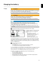
Page 25: ...he charger para meters Type of battery e g wet Charging characteristic e g IUI Nominal voltage e g 48 V Capacity e g 300 Ah Day of the week date and time The charger parameters can be set individually More information on the charger parameters can be found under Configuration mode in the Display functions chapter Ensure that the battery to be charged matches the configuration of the battery chargi...

Page 26: ...e already cooled down most If however the standard display is still to be shown rather than the minute counter 1 Use the Up Down keys to toggle between the minute counter and standard display When the battery is fully charged all 4 bars of the battery symbol appear black As soon as the battery is fully charged the charger begins conservation charging All bars are displayed The green Battery charge...

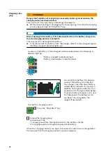
Page 27: ...s To resume the charging process 2 Press the Stop Start key again As long as a battery is connected to the charger only the charging process can be interrupted and resumed using the Stop Start key Display modes can be changed using the Menu key as described in the Display section but this is only possible when there is no battery connected to the charger 27 EN ...

Page 28: ...harged and has cooled down the following in dicators light up Battery charged indicator green Battery cooled down indicator blue For an optimal battery life only dis connect the battery from the bat tery charger when the blue Battery cooled down indicator is showing in addition to the green indicator in ac cordance with the explanation below If several battery chargers are in use first disconnect ...

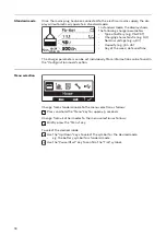
Page 29: ...ed during the charging process all using a USB flash drive As long as a battery is connected to the charger the charging process can only be interrupted and resumed using the Pause Start key Display modes can be changed using the Menu key as described in the following sections that explain the individual modes but this is only possible when there is no battery connected to the charger During a pau...

Page 30: ... date and time The charger parameters can be set individually More information can be found in the Configuration mode section Menu selection Change from standard mode to the menu selection as follows 1 Press and hold the Menu key for approx 5 seconds Change from all other modes to the menu selection as follows 1 Briefly press the Menu key To select the desired mode 2 Use the Up Down keys to select...

Page 31: ...toggle between page 1 2 and page 2 2 Page 2 2 shows the following values Total number of charges Total Ah output Average Ah output per charge Total energy consumed kWh Average energy consumed kWh per charge The consumed energy display is a standard value and can deviate from the actual amount of energy by up to 5 at nominal output At lower power levels the devi ation may be higher 31 EN ...

Page 32: ...oltage at charge end e g 48 0 V Ah consumed e g 397 Ah kWh consumed e g 19 kWh Charging characteristic e g 6 RI Set charging time e g 8 9 h or set Ah e g 400 Ah or set charge end time not shown Symbols shown 1 2 3 4 5 7 6 No Function 1 Full battery Charging has been completed 2 Empty battery Charging has not been completed 3 Exclamation mark with number Warning has been issued with the correspondi...

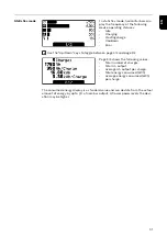
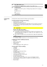
Page 33: ...of cells should only be set automatically for batteries with the following nominal voltages 12 V and 24 V for 24 V devices 24 V and 48 V for 48 V devices Do not set the number of cells automatically for deep discharged batter ies Additional settings for individual adaptation options for the charging characteristic Additional functions Additional functions Blue LED External start stop Refill indica...

Page 34: ...al number Software main software secondary software primary software and char acteristic block version The procedure for opening the configuration menu is as follows 1 Press the Pause Start key You will be prompted to enter a code The code required is 1511 and is entered as follows 1 Using the Up Down keys enter the first digit of the code 2 Press the Menu key to move to the next digit of the code...

Page 35: ...the Menu key to return to the higher level menu See the following explanation of how to set the charging settings by way of example 1 Use the Up Down keys to select the Charging settings menu item 2 Use the Pause Start key to confirm this menu item The choice of settings for the Charging settings menu item will now be dis played the display may vary depending on the selection made If the Pb WET ty...

Page 36: ...s in configur ation mode you will once again be prompted to confirm acceptance of the changed settings when exiting configuration mode The following settings need to be confirmed when exiting configuration mode Characteristic Battery capacity in Ah excluding the RI characteristic Number of cells Equalising charge ON OFF CAN protocol Example Changing the characteristic from 3 UI Pb WET to 6 RI Pb W...

Page 37: ...following settings are available for electrolyte circulation Off Electrolyte circulation switched off Continuous operation continuous Electrolyte circulation permanently on Program 1 to 5 Default electrolyte circulation programs and their relevant parameters can be found in the table under Settings in the Display chapter Automatic Automatic adjustment of electrolyte circulation flow rate based on ...

Page 38: ...e warning Equalising charge OFF There is no equalising charge Delay If the battery remains connected to the battery charger for the duration of the equalising charge delay equalize charge delay then a special type of charging takes place This prevents acid stratification The parameters for the current ampere 100 ampere hours voltage volt cell and duration of the equalising charge can be changed We...

Page 39: ...tion allows charging to be started automatically according to the following criteria Time window in which charging may not be started if a battery is connected Time window in which charging is to be started using a defined characteristic 1 if a battery is connected Time window in which charging is to be started using a defined characteristic 2 if a battery is connected 1 To activate the calendar f...

Page 40: ...ows If in the example above a battery is connected at 5 45 the charge end time is governed by the requirements of the battery and is not interrupted by the end time specified for the set time window 6 00 in the example If the battery is connected during the stop time window charging is started automatically during the next time window If charging is started manually during the stop time window cha...

Page 41: ...ted The repeat setting defines how often the alternative charging mode should be performed until the device reverts to the original charging parameters again Setting range 1 to 99 repetitions The following settings are also pos sible Characteristic e g Deep discharge 10 Number of battery cells Cells e g 12x Battery capacity in Ah e g 375 Ah Disable Start Button ON The charging process cannot be st...

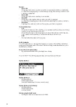
Page 42: ...gs are avail able Curve e g RI Pb Wet Charging time e g 5 6 h When opportunity charging is ON and a battery is connected the following appears Figure on left Display when RI characteristic is selected Figure on right Display for all other characteristics To start opportunity charging Use the Up key to select the runner symbol 1 1 Figure on left Runner symbol 1 Figure on right Display when opportun...

Page 43: ...be allowed to pass before the blue battery cooled in dicator comes on to indicate that a battery has cooled down sufficiently The time from the end of charging is used as the setting A temperature value can be set here in conjunction with the Temperature con trolled charging option The blue battery cooled indicator will light up to signal a sufficiently cooled battery once the temperature drops be...

Page 44: ...error 16 is set When Stop Normal is ON charging has started the external start stop con tact is open and the battery is not disconnected error 16 is set OFF Contact detection does not take place Refill Indicator The refill indicator is a message that appears as soon as the battery needs top ping up with distilled water The time at which refilling is deemed necessary can be defined as follows Every...

Page 45: ...s failure restart charging If this option is selected the charging process is restarted automatically as soon as the mains supply becomes available again after a disruption to the electrical mains supply 45 EN ...

Page 46: ...gs Contrast LED brightness Show Ah at charge end ON OFF Time and Date daylight saving time normal time Predefined time zones User defined time zones Charging cable Basic length of charging cable m Cable cross section Cross section of the charging cable mm AC current consumption Adapt the maximum consumed device current to the on site elec trical installation or the device connector fitted on the d...

Page 47: ...ure Temperature in C F Code Code entry required not required to access configuration mode Code ON OFF USB Logging Time Time interval s for recording charging parameters on the USB flash drive USB Logging Time Reset statistics Reset history For more detailed information on the statistics and history please refer to the Statistics mode and History mode sections 47 EN ...

Page 48: ...ormatting FAT32 32 Gigabyte maximum Non multi partitioned The I SPoT VIEWER software supports the visualisation and evaluation of data on the USB flash drive Only insert the USB flash drive when charging is not in progress of if the charging process has been interrupted If the charging process is only interrupted not completed it is only possible to read out data A new update or configuration cann...

Page 49: ... same way as for the Download function but is saved not in the I SPoT VIEWER format but as csv files Automatic folder structure for the csv files Fronius device serial number Charges yyyymmdd hhmmss csv Save events Events are saved to the USB flash drive Save configuration The device settings are saved to the USB flash drive Load configuration Loads onto the device one of the suitable device confi...

Page 50: ...ate More informa tion can be found in the USB mode section Status codes caused by external factors Number Cause 11 Mains overvoltage or undervoltage 13 External temperature sensor faulty 14 Electrolyte circulation faulty pressure switch not switching 16 External start stop is not closed 17 Open circuit voltage detection triggered more than once during charging e g worn charging contacts Status cod...

Page 51: ...ure 510 Primary EEPROM faulty 527 Phase shifter overcurrent 530 Communication error 532 Microcontroller error e g Division by 0 533 Reference voltage outside the tolerance 534 Start up error 535 PFC overcurrent 536 Phase shifter or PFC faulty Status codes in the event of a fault in the secondary circuit Number Cause 520 Secondary temperature sensor faulty 521 Secondary overtemperature 522 Fuse fau...

Page 52: ... fault in characteristic control 544 Program memory fault in characteristic control 545 Primary initialisation failed 546 Update failed 547 Load save settings failed 548 Load save characteristic settings failed 549 Charging process could not be continued after a power outage due to a fault in the backup battery 550 Time not set 551 Hardware change detected 552 CFM invalid 52 ...

Page 53: ...e for the optional component concerned all warning notices and instructions therein must be obeyed In the case of all optional components with electrical connections once the connection work is complete a safety inspection must be carried out in ac cordance with relevant national and international standards and directives Further details on safety inspections can be obtained from your authorised s...

Page 54: ...esult in a fault being detected then the status code Statecode 14 will appear on the display One way in which this fault can be indicated is by using an external indicator lamp to show a common error Weight of the electrolyte circulation set Air Puls air hose kit 3 kW C1 2 5 kg 5 51 lb Electrolyte circulation air filter insert The air filter insert for the integrated air pump should be cleaned onc...

Page 55: ...contacts and this arrangement safeguards more effectively against an oxyhydrogen explosion Temperature controlled char ging The temperature controlled charging option always adjusts the charging voltage according to the current temperature of the battery This results in considerably longer battery life especially where batteries are used in cold stores LED strip The LED strip acts as a status indi...

Page 56: ...and floor bracket with integrated cable holder ensures safe in stallation at the place of use Detailed information and diagrams can be found in under Wall and floor bracket in the General information chapter Mobile kit A carrying strap makes it easier to move the device Option box Using the option box information on the state of charge of the connected bat tery can be obtained via an external circ...

Page 57: ...98 342 13 74 370 13 86 376 14 96 115 4 53 6 5 26 38 1 5 38 1 5 53 8 2 12 53 8 2 12 6 5 26 6 5 26 76 2 99 205 8 07 76 2 99 14 55 6 5 26 14 55 425 16 73 482 18 98 115 4 53 428 16 85 456 17 95 462 18 19 415 16 34 418 16 46 446 17 56 452 17 80 6 5 26 38 1 5 38 1 5 53 8 2 12 53 8 2 12 6 5 26 6 5 26 76 2 99 205 8 07 76 2 99 14 55 6 5 26 14 55 mm in 3 kW C1 57 EN ...

Page 58: ...midity maximum 85 Maximum altitude above sea level 2000 m 6561 ft Mark of conformity according to rating plate Product standard EN62477 1 1 The device is approved for operation on neutral earthed networks 2 The thermal stress of the circuit breaker must not exceed 30 000 A2s 3 Interface to a 230 400 V and 50 Hz public grid 4 For indoor use only do not expose to rain or snow 5 A high ambient temper...

Page 59: ... 5 1 W EMC device class B Dimensions L x W x H 417 x 110 x 198 mm 16 42 x 4 33 x 7 8 in Degree of contamination 3 Degree of protection 4 IP21 Overvoltage category II Operating temperature 5 20 C to 40 C 4 F to 104 F Storage temperature 25 C to 80 C 13 F to 176 F Relative humidity maximum 85 Maximum altitude above sea level 2000 m 6561 ft Mark of conformity according to rating plate Product standar...

Page 60: ... 2080 3 kW 15 1 A 3040 W 24 V 80 A 8 2 kg 18 08 lb 2100 3 kW 15 3 A 3290 W 24 V 100 A 8 2 kg 18 08 lb 2120 3 kW 15 5 A 3340 W 24 V 120 A 8 7 kg 19 18 lb 4045 3 kW 15 0 A 3250 W 48 V 45 A 7 4 kg 16 31 lb 4060 3 kW 15 2 A 3280 W 48 V 60 A 7 4 kg 16 31 lb 6 With standard mains and charging leads 60 ...

Page 61: ...61 EN ...

Page 62: ...62 ...

Page 63: ...63 EN ...

Page 64: ......

Reviews: