Section 5 Component Teardown
5-6
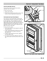
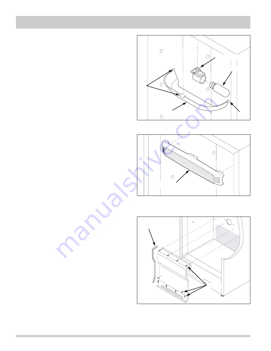
Figure 5-13. Light Shield and Fixture Removal
Light Shield Removal
The light shield is secured with retaining tabs that locate
in slots cut in the interior cabinet ceiling.
(See Figure 5-13)
To remove the light shield, grab the light shield and push
in near the retaining tabs until the retaining tabs release
from the slots in the compartment ceiling.
Light Fixture Removal
The light fixture is secured with retaining latches into the
interior cabinet ceiling behind the light shield.
(See Figure 5-13)
To remove the light fixture:
1. Remove light bulb by turning counter-clockwise.
2. Pull down on the front of the light fixture while
turning the fixture a quarter turn to release the
retaining latches.
3. Disconnect wire leads from light fixture terminals.
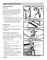
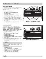
Baffle Plate Removal
The baffle plate is secured with four retaining latches to
slots in the compartment upper back wall.
(See Figure 5-14)
To remove the baffle plate, with one hand grab the
baffle plate from the center and pull back while with the
other hand, reach behind to disengage the retaining
latches.
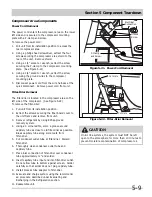
Evaporator Cover Removal
The evaporator cover is secured with screws to the back
wall and bottom of the freezer compartment. The evapo-
rator cover has a gasket on each side to create proper
airflow in the compartment. (See Figure 5-15)
To remove the evaporator cover:
1. Remove the bottom two shelf assemblies.
2. Remove the wire basket.
3. Using a phillips head screwdriver, extract the ten
(10) screws securing the evaporator cover to the
freezer compartment.
4. Carefully pull the evaporator cover away from the
back wall, using caution not to damage the gaskets
on both sides of the evaporator cover.
Light Shield
Tab
Tab
Light Fixture
Light Bulb
Figure 5-14. Baffle Plate Removal
Baffle Plate
Figure 5-15. Evaporator Cover Removal
Gasket
Screws
Summary of Contents for FFH17F8HW0
Page 2: ......
Page 14: ...Section 2 Installation Information 2 6 Notes ...
Page 18: ...Section 3 Electronic Control 3 4 Notes ...
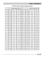
Page 33: ...Section 4 Refrigeration 4 15 HFC 134a CFC 12 Pressure Temperature Chart ...
Page 36: ...Section 4 Refrigeration 4 18 Notes ...
Page 48: ...Section 5 Component Teardown 5 12 Notes ...
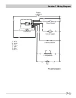
Page 53: ...Section 7 Wiring Diagram 7 1 ...

