Before continuing, please take note of the
WARNINGS
and
CAUTIONS
below.
- If it is necessary to remove a Freezer unit from its installation, use proper lifting techniques as units are heavy
and could fall resulting in serious injury or death. Pulling a unit from its installation should only be performed
by a trained authorized service technician or installer.
- To avoid electric shock, power to a freezer unit must be disconnected whenever accessing/ removing
components powered by electricity or components near other electrical components.
- After service is completed, be sure all safety-grounding circuits are complete, all electrical connections are
secure, and all access panels are in place.
- If unit was used prior to service, the Compressor assembly will be hot. Wear protective gloves and the
appropriate safety gear when working with compressors.
- If removing a door or drawer from a unit, remember that the doors and drawers are heavy. If they were to
fall, they could cause serious personal injury.
WARNING
- Metal edges may be sharp. Use caution and wear appropriate safety equipment when servicing
evaporators and condensers to avoid personal injury.
- If working in the compressor area, remember that compressor and tubing may be hot.
CAUTION
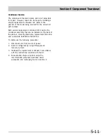
Section 5 Component Teardown
5-1
Component Teardown
This section explains how to access and remove components from a Kenmore Freezer, and has been arranged
in such a way as to simulate which components would need to be removed first in order to gain access to other
components. When following a component removal procedure, it may be necessary to reference another
component removal procedure listed earlier in this section.
IMPORTANT
Summary of Contents for FFH17F8HW0
Page 2: ......
Page 14: ...Section 2 Installation Information 2 6 Notes ...
Page 18: ...Section 3 Electronic Control 3 4 Notes ...
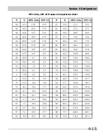
Page 33: ...Section 4 Refrigeration 4 15 HFC 134a CFC 12 Pressure Temperature Chart ...
Page 36: ...Section 4 Refrigeration 4 18 Notes ...
Page 48: ...Section 5 Component Teardown 5 12 Notes ...
Page 53: ...Section 7 Wiring Diagram 7 1 ...

