Section 5 Component Teardown
5-2
Exterior Components
Door Handle
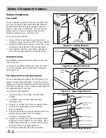
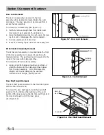
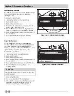
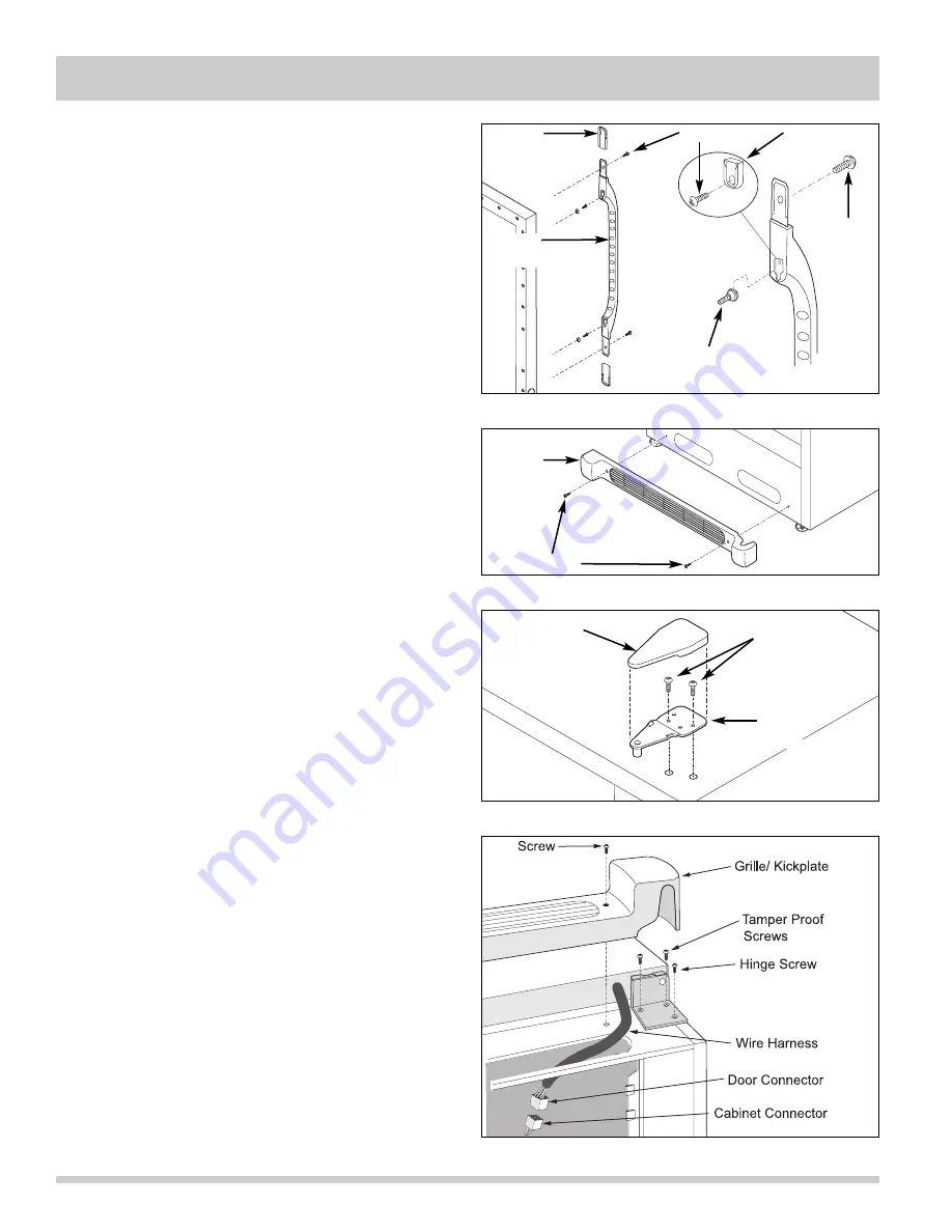
The door handle is secured to the door assembly with
two screw and button assemblies that slide behind a
dovetail block inside the handle assembly and with
screws on each end of the handle. Two screw cover
plates slide over the door handle to hide the door
handle mounting screws. (See Figure 5-1)
To remove the door handle:
1. Remove screw cover plates by pushing in and
sliding the screw cover plate off of the door handle.
2. Using a phillips head screwdriver, extract the screws
securing the door handle to the door assembly.
3. Push upwards until the screw button assembly is
free of the dovetail inside the handle assembly.
Kickplate Removal
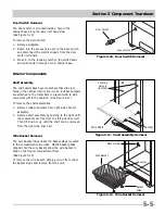
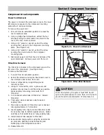
The kickplate is secured with two screws to the lower
front of the unit.
To remove the kickplate, extract the screw from each
end of the kickplate with a phillips head screwdriver.
(See Figure 5-2)
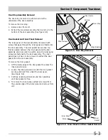
Door Hinge and Door Assembly Removal
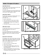
The door assembly is secured to the unit frame by an
upper and lower hinge assembly. The wiring harness
leading out of the door assembly must be disconnected
from the wire harness in the compressor area before the
door assembly can be removed.
To remove the door assembly:
1. Gently lay freezer on its back on a soft clean
surface.
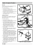
2. Lift plastic cover off upper hinge assembly.
(See Figure 5-3)
3. Using a T27 tamper proof Torx bit, extract screws
securing the upper hinge to the unit frame.
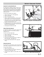
4. Remove kickplate.
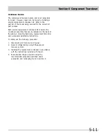
5. Reach under bottom of cabinet and disconnect wire
leads of door connector from the cabinet
connector. (See Figure 5-4)
6. Using a T27 tamper proof Torx bit, extract screws
securing the lower hinge to the unit frame. Use a
phillips head screwdriver to extract the remaining
screw from the lower hinge assembly.
7. Lift the door assembly off of the unit frame.
Figure 5-1. Handle Removal
Figure 5-2. Kickplate Removal
Kickplate
Handle
Trim
DovetailB
lock
Screw and
Button Assembly
Screw
Screw
Handle
Assembly
Screws
Figure 5-4. Lower Hinge Removal
Figure 5-3. Upper Hinge Removal
Screws
Upper
Hinge
Hinge
Cover
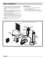
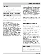
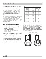
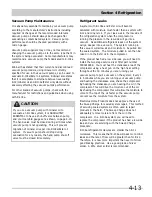
Summary of Contents for FFH17F8HW0
Page 2: ......
Page 14: ...Section 2 Installation Information 2 6 Notes ...
Page 18: ...Section 3 Electronic Control 3 4 Notes ...
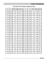
Page 33: ...Section 4 Refrigeration 4 15 HFC 134a CFC 12 Pressure Temperature Chart ...
Page 36: ...Section 4 Refrigeration 4 18 Notes ...
Page 48: ...Section 5 Component Teardown 5 12 Notes ...
Page 53: ...Section 7 Wiring Diagram 7 1 ...

