Section 3 Electronic Control
3-2
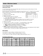
Service Diagnostic Mode
Initiate Service Mode
To enter the Service Mode, lock the keyboard then press and hold the up arrow and the down arrow for three
seconds (until the display changes to "8").
When the diagnostics mode is entered, the compressor is turned off and the digit "8" is displayed for three seconds.
After three seconds, the sequential information below will be displayed.
1. Blank for 0.5 seconds
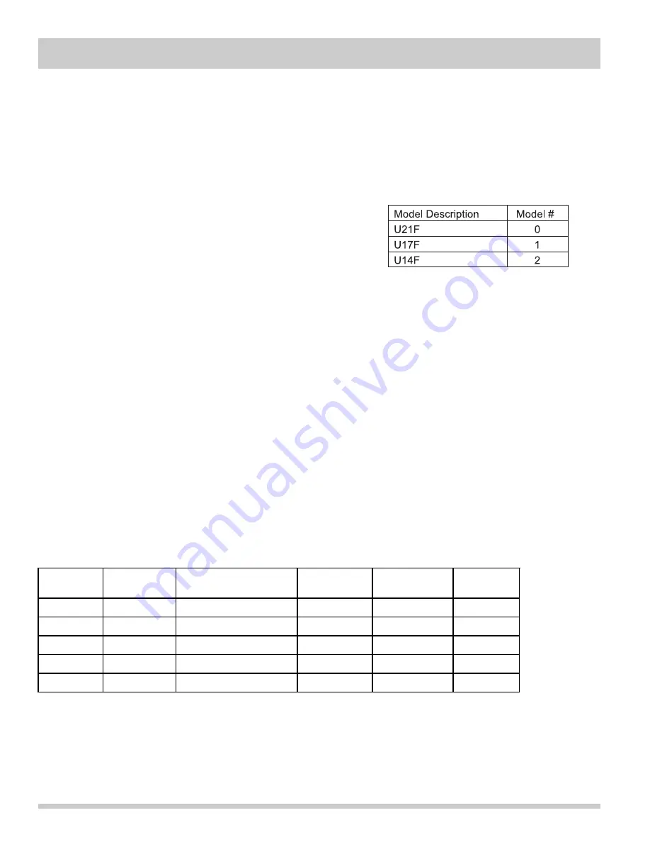
2. Model ID for 1 second (See Table)
3. Blank for 0.5 seconds
4. Software Version and LED test for 3 seconds.
a. Hi Temp LED illuminates during display of 1st digit of
the version number for one second,
b. Door Ajar LED illuminates during display of 2nd digit of the version number for one second.
c. Both LED's illuminate during display of 3rd digit of the version number for one second.
5. Blank for 0.5 seconds
6. Thermistor status ("0" for open, "C" for close or "-" for good thermistor) for three seconds.
7. 10 seconds for power check. During this time each key activates a specific load.
a.
UP
key activates the compressor and lowercase "c" is displayed.
b.
DOWN
key activates defrost heater and lowercase "d" is displayed
8.
MUTE
key activates the light and lowercase "l" is displayed.
10 seconds after the last key press, the system will exit the diagnostic mode, automatically assuming the default
temperature setting. If required, the compressor restarts after 13 minutes.
Error Modes
If the thermistor is open, the display will alternate between "E" and "9".
If the thermistor is shorted, the display will alternate between "E" and "8".
If a key is stuck for more than 30 seconds, the display will alternate between "E" and "7".
Thermistor Resistance Chart
Temp °C
Temp °F
Nominal Resistance Max. Ohms
Min. Ohms
Tolerance
Ohms
% +/-
0°
32°
32,654
33,604.72
31703.29
2.91
-15°
5°
72,940
75,283.21
70,596.79
3.21
-20°
-4°
97,060
100,283.44
93,836.56
3.32
-30°
-22°
177,000
183,293.70
170,706.30
3.55
-40°
-40°
336,000
349,139.51
322,860.49
3.91
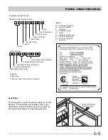
Type (Found on Serial Plate)
Summary of Contents for FFH17F8HW0
Page 2: ......
Page 14: ...Section 2 Installation Information 2 6 Notes ...
Page 18: ...Section 3 Electronic Control 3 4 Notes ...
Page 33: ...Section 4 Refrigeration 4 15 HFC 134a CFC 12 Pressure Temperature Chart ...
Page 36: ...Section 4 Refrigeration 4 18 Notes ...
Page 48: ...Section 5 Component Teardown 5 12 Notes ...
Page 53: ...Section 7 Wiring Diagram 7 1 ...


