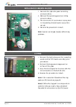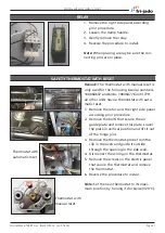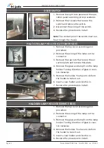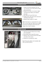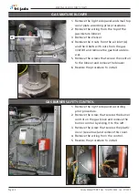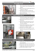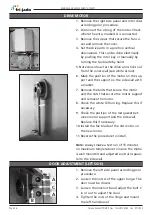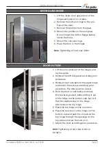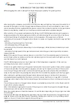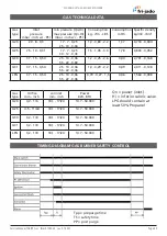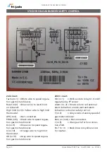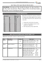
REMOVAL AND REPLACEMENT OF PARTS
Page 28
Service Manual TDR8 P Gas form 9124023 rev. 01/2022
1. Remove the right side panel and operating
panel according prior procedures.
2. Disconnect the wiring.
3. Remove on the front side the 2 screws and
on the inside the nut that secure the panel.
4. Remove on the inside bottom of the electric
panel the bolt and nuts.
5. Slide the electric panel backwards to remo-
ve this.
6. Reverse the procedure to install.
1. Remove the right hand panel according
prior procedure.
2. Remove the operating panel according
prior procedure.
3. Remove the USB connection, the reset
switch and the red indicaton light.
4. Remove the 4 nuts and rings on the CPU
board and remove the board.
5. Reverse the procedure to install.
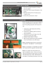
Note 1:
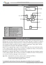
For connection flatcable of the key-
pads see CPU board on page 28.
Note 2:
For older units with earth wire in right
hand bottom corner. Take care that the ring
terminal doesn’t make contact with with the
solder point (see arrow) .Otherwise the illumi-
nation of the display and keys can be out.
ELECTRIC PANEL
OPERATING PANEL, GLASS + BAC KEYPAD
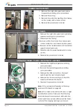
1. Remove the right side panel and opera-
ting panel according prior procedures.
2. Remove the wiring.
3. Remove the switch by pushing the clamps,
on the inside, with a screw driver.
4. Reverse the procedure to install.
TUMBLE SWITCH RESET

