background image

69

|  OPERATION MANUAL

to use to pair the MIMIC with your MōVI Pro.

RADIO

BIND

SELECT

CHANNEL

-

STATUS

-

SIGNAL

STRENGTH

4. 

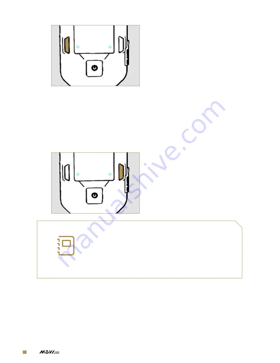
Turn on the MōVI Pro and proceed to the Radio Screen.  Use “Select 
Channel” to set the MōVI Pro to the same channel as the MIMIC. Press 
the Bind button on the MōVI Pro; a progress bar will appear showing 
the amount of time remaining to pair the device to a MIMIC.

5. 

Press the Bind button on the MIMIC within 5 seconds of pressing the 
Bind button on the MōVI Pro. The devices will pair automatically.


RADIO

BIND

SELECT

CHANNEL

-

STATUS

-

SIGNAL

STRENGTH


NOTE

MIMIC uses a very powerful wireless transmitter 
to control the MoVI Pro; when this transmitter is 
in close proximity to its receiver, the receiver 
can be oversaturated with input causing unwanted 
movements or binding issues. This is normal 
behavior for power wireless transmitters.

MIMIC BETA + MōVI PRO

The MIMIC Beta Controller comes pre-bound to the Freefly Receiver included in the MIMIC Beta 
package. If you are using the bound receiver provided with the MIMIC Beta, follow steps 1-4 to 
connect and power both products.  Users trying to bind a MIMIC Beta to a unbound receiver must 
follow all steps 1-9.

Summary of Contents for movi pro

Page 1: ...OPERATION MANUAL 770 00050 REVISION B 03 01 2017...

Page 2: ...To download the most current user manual for the M VI Pro and all other Freefly products please visit http freeflysystems com software manuals freeflysystems freeflyers...

Page 3: ...3 OPERATION MANUAL REVISION HISTORY REVISION DATE DESCRIPTION A Nov 2016 Initial Release B Mar 2017 Add section on M VI Ring Pro M VI Pro and minor content edits...

Page 4: ...and piNouts 24 Tilt Stage Unit connectors and pinouts 28 System Diagrams 28 M VI Pro Overview 29 M VI Pro Control Paths 30 M VI Pro Power System 31 M VI Pro Mimic 32 M VI Pro App 33 M VI Pro Kit 34 SE...

Page 5: ...Pro 72 M VI CONTROLLER M VI Pro 74 Futaba or Spektrum Radio M VI Pro 74 Multi Controller Setup 75 ALTA M VI Pro 79 TERO M VI Pro 80 M VI Ring Pro M VI Pro 84 USING M VI PRO 85 Configuring the M VI Pro...

Page 6: ...l position Gyro Gyros are sensors that measure the angular velocity of an object they are mounted on HACC A GPS value indicating the horizontal accuracy HACC of the position fix HDMI High Definition M...

Page 7: ...he M VI Pro that provides orientation feedback to the GCU and can provide power and control to the camera and mounted accessories TX TX is an acronym for transmit or transmitter uART A universal async...

Page 8: ...Overview OVERVIEW...

Page 9: ...full system check of M VI Pro prior to every use It is your responsibility to learn how to safely operate M VI Pro M VI Pro is a tuned system with custom components selected for each application Mod i...

Page 10: ...re than two M VI Pro Battery Packs should be placed in a container to avoid chain reactions The recommended storage temperature range is 10 C to 26 C Exposure to high tempera tures may cause fire even...

Page 11: ...ger may cause damage to the batteries or a fire Never charge or use a M VI Pro Battery Pack that shows any damage or disfigurement of any kind as this may be a sign of internal damage Any damage to th...

Page 12: ...with the battery 1 Contact your state or local HAZMAT agency inquire about disposal procedures for LiPo batteries with battery management systems 2 Follow any instructions provided by your state or lo...

Page 13: ...PARTY CLAIMS AGAINST BUYER THESE LIMITATIONS SHALL APPLY NOTWITHSTANDING ANY FAILURE OF ESSENTIAL PURPOSE OF ANY LIMITED REMEDY THE LIMITATION SET FORTH IN THIS SECTION SHALL APPLY WHERE THE DAMAGES...

Page 14: ...rants that M VI Pro Battery Packs purchased or included with the Product will be free from defects in materials and workmanship at the date of purchase by Buyer Battery product warranty is limited to...

Page 15: ...RANTY TORT NEGLIGENCE STRICT LIABILITY OR ANY OTHER THEORY OF LIABILITY EVEN IF FREEFLY HAS BEEN ADVISED OF THE POSSIBILITY OF SUCH DAMAGES IN NO EVENT SHALL THE LIABILITY OF FREEFLY EXCEED THE INDIVI...

Page 16: ...nual will teach you how to set up balance and tune your M VI Pro It also includes detailed descriptions of the M VI Pro s features and capabilities to familiarize you with the possibilities of using i...

Page 17: ...nal Wiring Updated wiring is now internally routed and strain relieved preventing damage to cables and enhancing reliability in a variety of weather conditions 5 Aerial Ready Go from handheld to aeria...

Page 18: ...FIZ Control Utilizing the world s smallest fully integrated 3 axis FIZ controller the M VI Pro reduces shooting weight and FIZ setup time with all industry standard motors SOFTWARE FEATURES 13 M VI P...

Page 19: ...Roll Rate 360 s Max Tilt Rate 360 s Weight 2 65kg Max Payload 6 80kg Max Operating Speed 100km hr dependent on payload Operating Temperatures 20 to 50 C Ingress Protection IP52 dust water droplet pro...

Page 20: ...0 OPERATION MANUAL GCU AND TSU LAYOUTS GIMBAL CONTROL UNIT 2 1 3 4 5 6 GCU LAYOUT 1 Power Button a Push ON b Hold OFF 2 Back Button 3 Forward Button 4 Select Option 5 Select Option 6 microSD Card Slot...

Page 21: ...21 OPERATION MANUAL 2 1 3 GCU CONNECTOR LAYOUT 1 COM 1 2 12V 3 COM 2...

Page 22: ...22 OPERATION MANUAL TILT STAGE UNIT 2 1 3 4 5 6 7 8 9 10 TSU CONNECTOR LAYOUT 1 TC 2 EXP 3 CAN 4 CAM 5 12 14V CAM 6 12V AUX 7 Focus 8 Iris 9 Zoom 10 USB C DRP...

Page 23: ...of the connectors on the GCU and TSU unless stated otherwise CONNECTOR COM 1 TYPE JST GH 6 PIN 2 1 3 4 5 6 1 GND 2 5V 3 UARTn_TX 4 UARTn_RX 5 UARTn_CTS 6 UARTn_RTS CONNECTOR 12V TYPE FEMALE D TAP 1 12...

Page 24: ...TSU unless stated otherwise CONNECTOR TC LTC TIMECODE TYPE 3 5MM JACK 2 1 3 4 Shown from Function Side of the male 3 5mm Jack 1 Base Mic LTC IN 2 Ring Gnd GND 3 Ring Right SYNC IN 4 Tip Left LTC OUT C...

Page 25: ...PIN 2 1 3 4 1 GND 2 V Ba 3 CAN H 4 CAN L CONNECTOR CAM CAMERA TYPE MOLEX MICROFIT RA 8 PIN 1 2 3 4 5 6 7 8 1 GND 2 5V 3 RxD 4 TxD 5 LANC Power 6 LANC Signal 7 GPO UART TX 8 GPI UART RX CONNECTOR 12 1...

Page 26: ...1 12V DTAP V 2 12V DTAP GND CONNECTOR F FOCUS MOTOR TYPE MOLEX MICROFIT RA 6 PIN 1 2 3 4 5 6 1 Motor A 2 Motor B 3 5V 4 GND 5 Encoder A 6 Encoder B CONNECTOR I IRIS MOTOR TYPE MOLEX MICROFIT RA 6 PIN...

Page 27: ...27 OPERATION MANUAL CONNECTOR Z ZOOM MOTOR TYPE MOLEX MICROFIT RA 6 PIN 1 2 3 4 5 6 1 Motor A 2 Motor B 3 5V 4 GND 5 Encoder A 6 Encoder B CONNECTOR USB PORT TYPE USB TYPE C DRP SOURCE AND SINK 5V...

Page 28: ...28 OPERATION MANUAL SYSTEM DIAGRAMS M VI PRO OVERVIEW N O T I N C L U D E D GPS Satellite M VI Pro App 2 4GHz M VI Controller MIMIC Radio Controller HD Video Link Preview Monitor...

Page 29: ...29 OPERATION MANUAL M VI PRO CONTROL PATHS Gimbal Control Unit Tilt Stage Unit M VI Controller Receiver Tilt Motor Roll Motor Pan Motor 2 4GHz M VI Controller MIMIC Radio Controller...

Page 30: ...30 OPERATION MANUAL M VI PRO POWER SYSTEM Gimbal Control Unit Tilt Stage Unit Intelligent Batteries Tilt ESC Roll ESC Pan ESC 12v Aux 12v Aux i e Transmitter Camera...

Page 31: ...31 OPERATION MANUAL M VI PRO MIMIC MIMIC mounted to handlebar stand alone etc M VI Pro Handheld on ALTA on TERO etc P a n R o l l T i l t...

Page 32: ...32 OPERATION MANUAL M VI PRO APP M VI Pro App Bluetooth Low Energy 0 0 0 0 0 1 Majestic Dual Op Tuning Timelapse Target...

Page 33: ...FRX Cable 8 M VI Rod Mount Adapter 9 2 Bolt 3 8 16 x 5 8 10 2 Bolt 20 x 11 2 Bolt 20 x 3 8 12 2 0mm Hex Driver 13 2 5mm Hex Driver OPTIONAL ACCESSORIES 14 M VI Ring Pro 15 M VI Classic Handle 16 MIMI...

Page 34: ...34 OPERATION MANUAL Setting Up M VI Pro SETTING UP M VI PRO...

Page 35: ...unting a Canon C series Camera 46 Mounting a Black Magic Cinema Camera 47 Mounting the Camera Package 53 Wiring Guide 56 Balancing the M VI Pro 59 Tuning the M VI Pro 63 Updating the M VI Pro 67 M VI...

Page 36: ...E QUICK RELEASE TITH Quick Release is a sleek lightweight low profile quick release unit which provides an easy mount and release solution for all your Freefly products MOUNTING PROCEDURE 1 Open the l...

Page 37: ...I Pro securely and close the TITH s lever while making sure that none of the release buttons are pressed This concludes the TITH mounting procedure CAUTION Always check to see whether the TITH has eng...

Page 38: ...ly in one hand so the gimbal does not fall during the release process 2 While supporting the M VI Pro open the lever and press the two release buttons on the TITH simultaneously 3 The male and female...

Page 39: ...low the charging procedure below to maintain a safe charging environment M VI PRO BATTERY PACK CHARGING PROCEDURE 1 Insert the AC power cord into AC power adapter and plug the power cord into a 120 VA...

Page 40: ...to GREEN your battery is fully charged Press the power button on the battery to check the power level and disconnect the battery from the charger CAUTION For all warnings concerning the batteries and...

Page 41: ...stall and remove your camera package The camera rail is also used to adjust the balance of the camera package BASIC SETUP These instructions will teach you how to quickly set up most DSLR and Mirrorle...

Page 42: ...balancing process HOT SHOE AND TOP RAIL Items Needed Camera Package Top Rail Hot Shoe Adapter 2 M3 Screw 2 5mm Hex Driver 1 Loosen the Hot Shoe Adapter located on one end of the top rail and insert it...

Page 43: ...arately These items are not included with the M VI Pro 1 If necessary mount lens gears over the focus zoom or iris rings of the lens 2 Mount the camera lens onto the camera by following the specific l...

Page 44: ...Top Rail V lock Adapter Kit for ALEXA Mini 3 20 Bolt 8 M4 Screw 4 4mm 5 32 Hex Driver 3mm Hex Driver These items are not included with the M VI Pro 1 Attach the aluminum mounting plates from the V Loc...

Page 45: ...otor to the camera package MOUNTING SONY CAMERAS TO THE CAMERA RAIL Items Needed Camera Package Camera Rail Top Rail 20 Bolt 2 3 8 16 Bolt 5 32 Hex Driver 7 32 Hex Driver These items are not included...

Page 46: ...Bolt 3 8 16 Bolt 5 32 Hex Driver 7 32 Hex Driver 2 5mm Hex Driver These items are not included with the M VI Pro 1 Locate one 20 one 3 8 16 bolt and the camera rail from the M VI Pro kit 2 Align the c...

Page 47: ...ail to the 20 bolt hole on the bottom of the Black Magic camera Insert and tighten the bolts until the camera is secured and has no play See the diagram for suggested camera rail placement Lens Direct...

Page 48: ...od mount can be attached with the arms pointing up or down The mount orientation will depend on the length of the FIZ motors and the diameter of the lens on the camera 2 Measure the distance from the...

Page 49: ...f the ring clamps on the rod mount Once the carbon fiber rod is flush with the back of the rod mount tighten the M3 screw to secure the rod in place 4 Mount and position your FIZ motors on the carbon...

Page 50: ...5 32 Hex Driver These items are not included with the M VI Pro 1 Open the clamp on the Pop n Lock and attach it to one of the suggested transmitter mounting locations Make sure the mount faces away fr...

Page 51: ...51 OPERATION MANUAL 3 Slide the plate into the Pop n Lock base to mount the transmitter to the M VI Pro 4 Rotate the latch on the Pop n Lock to secure the transmitter...

Page 52: ...NUAL MOUNTING A MONITOR Items Needed M VI Ring Pro Monitor Mount Monitor These items are not included with the M VI Pro 1 Use the 20 bolt on the M VI Ring Pro handle to mount your preferred monitor or...

Page 53: ...s on the top horizontal crossbar and move the bar up so the camera has room to fit in the cage 2 Open the top and bottom camera rail toggle clamps and rotate the top toggle 90 degrees counterclockwise...

Page 54: ...ar 5 Make sure the top camera rail is engaged with the locking mechanism and twist the top toggle 90 degrees clockwise and close the clamp 6 The camera package is now mounted If you are using a monito...

Page 55: ...l four rails engage and the battery slides smoothly along the tray 2 Push the battery until the connectors are fully engaged and the battery locks into place 3 To remove the battery lift up on the bat...

Page 56: ...le MicroFit 8 Pin Double Row 2 5MM Stereo Jack Freefly Lens Motor Cable Right Angle MicroFit 6 Pin Double Row LEMO 1B 7 Pin Freefly Lens Motor Cable Straight MicroFit 6 Pin Double Row LEMO 1B 7 Pin Fr...

Page 57: ...ontrol Gimbal Camera CAM LANC Freefly LANC Control Cable FIZ Motor Power and Control Gimbal FIZ Motor F I Z FIZ Motor Connector Freefly Lens Motor Cable Transmitter Power Gimbal Transmitter 12V AUX DC...

Page 58: ...tor F I Z FIZ Motor Connector Freefly Lens Motor Cable Transmitter Power Gimbal Transmitter 12V AUX DC IN Freefly Connex Power Cable DTap LEMO 0B 2 Pin Paralinx Tomahawk Video Signal Camera Transmitte...

Page 59: ...es afterward will require the system to be rebalanced for optimal performance Remove protective covers such as lens caps that will not be used while shooting before balancing the system Items Needed M...

Page 60: ...ge up or down until the camera remains pointing straight up when released 4 Close the toggle clamps 5 Confirm tilt balance by moving the camera to several tilt angles and confirming the camera remains...

Page 61: ...ch that the camera lens is lined up with the handle bar s cross beam 3 Use the handle to tilt the M VI Pro 5 to 10 degrees and observe which way pan rotates a If the lens points to the low side it ind...

Page 62: ...d as indicated in Step 3 and repeat the process until the gimbal does not swing left or right when tilting about the pan axis 6 Close the two pan toggle clamps and confirm that the camera does not swi...

Page 63: ...the Tuning Menu under Configurations 5 In order for Autotune to work properly the camera should be completely free to move 6 The Autotune feature s margin of error can be adjusted to reach a higher Au...

Page 64: ...e second most important setting for achieving maximum stabilization performance The purpose of the filters is to eliminate noise and vibration due to structural resonances in the camera lens or gimbal...

Page 65: ...trength has pros and cons that should be considered depending on the shooting situation Higher Hold Strengths PROS Better rejection of disturbances such as wind cable tugging and inertial forces due t...

Page 66: ...e of camera movement can be used to enable higher Hold Strengths while reducing the possibility of overshoot This is especially helpful when shooting with longer focal lengths Tuning Max Control Rate...

Page 67: ...m the App Store or Google Play 2 Turn on the M VI Pro and make sure it is fully charged and has finished booting 3 Open the M VI Pro app on your mobile device and it connect to the M VI Pro 4 If there...

Page 68: ...lay with controls upgraded processor and new features make it the most intuitive camera controller available To use a MIMIC with your M VI Pro you will first have to pair the devices as described in t...

Page 69: ...es will pair automatically RADIO BIND SELECT CHANNEL STATUS SIGNAL STRENGTH NOTE MIMIC uses a very powerful wireless transmitter to control the MoVI Pro when this transmitter is in close proximity to...

Page 70: ...and Freefly RX are set to the same channel The channel is set by a small dial located on the TX and RX 2 Ensure the Freefly RX s 5 pin connector is plugged into the COM1 port on the M VI Pro GCU 3 En...

Page 71: ...y RX for 2 3 seconds before releasing it 6 Wait for the RX s status LED to slowly flash orange This indicates the TX has been found 7 Press and hold the Bind button on the MIMIC Beta TX until the stat...

Page 72: ...s SETTING UP M VI CONTROLLER AND M VI PRO Items Needed M VI Pro M VI Controller M VI RX These items are not included with the M VI Pro 1 Select the desired channel on M VI RX and connect it to the COM...

Page 73: ...Set knob 7 Press Menu Set knob to enact Bind command 8 Wait 20 seconds until M VI Controller and M VI RX are bound NOTE For instructions on the operating procedure and other information on the M VI Co...

Page 74: ...This means a MIMIC can be used to control gimbal orientation while simultaneously operating a camera s FIZ through M VI Controller M VI CONTROLLER MIMIC M VI PRO 1 Setup MIMIC and M VI Pro as describ...

Page 75: ...Pro can be mounted on top of the ALTA in SkyView or underneath the ALTA in GroundView NOTE To use the M VI Pro in Skyview do not attach the M VI Pro Aero Landing gear to the M VI Pro CAUTION Make sur...

Page 76: ...h the long carbon fiber tubes to the landing gear cross beam to assemble the front landing gear Use the levers to hand tighten the rods into place 2 Place M VI Pro on a M VI Dock and use four M3 screw...

Page 77: ...not require excessive force Always slide the rear landing gear into its slot using a lateral motion GROUNDVIEW Items Needed M VI Pro Landing Gear ALTA These items are not included with the M VI Pro 1...

Page 78: ...dy SKYVIEW Items Needed M VI Pro ALTA ALTA SkyView Landing Gear These items are not included with the M VI Pro 1 Attach SkyView landing gear to the ALTA using the TITH connector underneath the ALTA 2...

Page 79: ...the operating procedure and other information on the ALTA please visit freeflysystems com software manuals and download the ALTA Aircraft Flight Manual TERO M VI PRO Place the M VI Pro in the middle...

Page 80: ...more quickly and effectively than ever before SETTING UP M VI RING PRO AND M VI PRO Items Needed M VI Pro M VI Ring Pro 2 5mm Hex Driver Set of M VI Ring Pro Feet 10 M3x8 6 M3 Nylon Lock Nuts 2 Grip...

Page 81: ...Use the hex driver to fasten the foot to the M VI Ring Pro using 3 M3x8 bolts and 3 nylon lock nuts Repeat steps 1 2 with the second foot 3 Wrap the grip tape around the carbon tube in your preferred...

Page 82: ...4 M3x6 screws to attach the M VI Pro Low Profile Handle to the Ring Pro to it faces in the same direction as the M VI Ring Pro feet 6 Attach your M VI Pro using the TITH and confirm that the TITH is...

Page 83: ...Pro feet make sure that they are angled outward and the ring leans forward 4 degrees when placed on a flat surface Improper attachment of the M VI Ring Pro s feet can lead to instability and potentia...

Page 84: ...84 OPERATION MANUAL Using M VI Pro USING M VI PRO...

Page 85: ...g the M VI Pro is easy With a built in control screen and mobile app that can assume complete control over the M VI Pro s settings a user can adjust tuning values remote controller setup and switch mo...

Page 86: ...ils including warnings and device status OPTIONS DESCRIPTION 1 Left Battery Power Displays the power remaining in the left battery as a percentage 2 Right Battery Power Displays the power remaining in...

Page 87: ...er device Autotune Screen OPTIONS DESCRIPTION 1 Percentage Set Autotune percentage a higher value will result in a configuration closer to the max stiffness 2 Start Initiates the autotuning feature on...

Page 88: ...lues 4 Filter Values Pan Roll Tilt Displays a visual of the Pan Roll or Tilt filter values 5 Next Screen Button Takes users to the next GCU screen 6 Previous Screen Button Takes users to the previous...

Page 89: ...at the middle of the Pan Roll and Tilt bars on the balance screen OPTIONS DESCRIPTION 1 Pan Roll and Tilt Visuals Displays the real time motor activity needed to maintain camera stability 2 Pause Acti...

Page 90: ...3 Next Screen Button Takes users to the next GCU screen 4 Previous Screen Button Takes users to the previous GCU screen RADIO SCREEN This screen allows users to select the M VI Pro s receiver channel...

Page 91: ...to create a configuration of the current settings Once created the configuration can be renamed applied or deleted through the Presets menu CONNECTION TO THE M VI PRO USING BLE Before you can use a m...

Page 92: ...Trim Increase or decrease the roll trim angle to level the camera during Majestic Mode 3 Pan Trim Increase or decrease the pan trim angle and set a new neutral pan angle when the M VI Pro is hard mou...

Page 93: ...ss calibration 4 Motion Booting Enable Motion Booting to allow M VI Pro to boot in situations where there is significant movement during the initialization process of the gimbal such as on a boat For...

Page 94: ...use the correct signal protocol when communicating with the camera This must be done in addition to using the correct remote R S or control cable Focus Scale Set the focus scale to Linear or Stretched...

Page 95: ...and other settings that are specific to the motor Dampening Change the strength of the low pass filter being used on the input control knob Knob Direction Change the control direction of the input in...

Page 96: ...de GUI allows a user to configure the Majestic Mode to suit a particular shot OPTIONS DESCRIPTION 1 Tilt Smoothing Adjust the smoothing value applied to the tilt axis Smaller values will result in gim...

Page 97: ...be ignored by the M VI Pro in Majestic Mode This will allow for unintentional movements to be ignored TIMELAPSE MODE Timelapse mode lets users create stunning camera movements for timelapses in secon...

Page 98: ...o exit the keyframe editing mode NOTE M VI Pro Keyframe positions may be set by hand or remotely via the M VI Controller or an authorized 3rd party radio controller Setup Panel OPTIONS DESCRIPTION 1 T...

Page 99: ...ree position switch to control modes Kill Majestic Dual Op 4 Pan Select the radio channel for pan It is recommended that the pan should be mapped to the right joystick s horizontal axis 5 Pan Rate Sel...

Page 100: ...Rate 1 Map Remote Tilt 3 Map Remote Tilt Rate 7 Map Remote Roll Trim 4 Mapping for Futaba Transmitter RADIO TYPE S BUS Map Pan Rate Clamp 7 Map RC Mode 5 Map RC Pan 1 Map RC Roll Trim 4 Map RC Tilt 2...

Page 101: ...l other situations Remote Rate Scale Select the Remote Rate Scale value A higher value will increase the maximum pan and tilt rates when in Dual Op mode Pan Joystick Smoothing Sets how much smoothing...

Page 102: ...a specific location and altitude Target MIMIC mode will target the location of the bound MIMIC 3 Height Offset Select a height offset for Pos Alt mode 4 Target Mode Mark a the GPS location that M VI...

Page 103: ...103 OPERATION MANUAL Troubleshooting and Maintenance TROUBLESHOOTING AND MAINTENANCE...

Page 104: ...OSSIBLE CAUSE POSSIBLE SOLUTION Stiffness setting is too high Reduce the Stiffness setting of the axis that is oscillating using the Tuning menu on the GCU or M VI Pro app An Adjustment Clamp is not t...

Page 105: ...POSSIBLE CAUSE POSSIBLE SOLUTION Dual Operator Radio Controller is off or set to Kill or Majestic Mode Turn on Radio Controller and set Mode Switch to Dual Operator DUAL Mode Radio Controller Mapping...

Page 106: ...106 OPERATION MANUAL Appendix APPENDIX...

Page 107: ...e Tilt Rate RC Channel 7 Max Control Rate 200 deg s Max Roll Angle 45 deg Max Tilt Angle 70 deg Min Tilt Angle 110 deg Output Filter 1 Output Pan Filter 10 Output Roll Filter 5 Output Tilt Filter 1 Pa...

Page 108: ...T VALUE Target Height Offset 0 m Tilt Hold Strength 30 Tilt Joystick Expo 10 Tilt Joystick Smoothing 5 Tilt Joystick Window 8 s Tilt Majestic Pan 135 deg Tilt Smoothing 10 Tilt Stiffness 0 Tilt Trim 0...

Page 109: ...ement to the North Pitch deg The IMU derived pitch angle where positive values indicate pitch up Pitch Rate deg s The IMU derived pitch rate where positive values indicate an upward pitch Radio Pitch...

Page 110: ...aw in the clockwise direction Yaw Rate deg s The IMU derived yaw rate where positive values indicate a clockwise rotation To download the most current user manual for the M VI Pro and all other Freefl...

Reviews: