Forza FDC-106K User Manual Download Page 8

Note: 

0 = no jumper; 1 = connect with jumper

13. Changing charging current

1) This operation should only be performed by trained and qualified technicians.

2) Turn off the UPS. If the load couldn’t be cut off, you should remove the cover of maintenance bypass switch on the rear  


    panel and turn the maintenance switch to the BPS position first. 

3) Switch off the input breaker.

4) Remove the cabinet cover, and disconnect battery wire. Then modify the jumpers on the charger board to set the charging      

    current (refer to table below). Be careful that the maximum setting should not exceed the charging current acceptable for the     

    battery.

3.5 Parallel operation

UPS installation for parallel systems

If the UPS is only available for single operation, you may skip this section to the next.

 1. Please follow the instructions to make sure the UPS systems are correctly wired for parallel operation. Refer to the

     illustration below:


Charge current (A)

1A


2A


3A


4A


JP06

JP07

JP08

0

0

1

0

1

0

1

0

0

0

0

0

1. Failure to connect the Non-isolated neutral between each UPS may permanently damage the units.

2. Connect the output of each UPS to an output breaker.

3. Connect all output breakers to a main breaker. The latter is the one that will be connected to the loads.

4. If using external power banks, each UPS must be connected to its own power bank. In the event a single power bank is used  

    for all the UPS units, it will cause permanent damage to the equipment.

5. Connect both parallel cables between each UPS, the communications cable (DB-25) and the load balancing cable, as  


    illustrated below:

Once the above connections are completed, verfify that the following conditions are met:

1. Verify that the input voltage is the same for all UPS units (208, 220, 230 o 240V)

2. Turn on the UPS and the battery breaker located on the back panel of the UPS.

3. If the configuration is successful, the following screen will be displayed in all UPS units.

4. Verify the output voltage in Bypass mode using one enabled output breaker.

5. Next, turn the other output breaker on making sure that output is the same ouput in every UPS. The output difference among  

    all UPS units must not exceed 1V.

6. Once you have checked all the above, turn OFF all the UPS units and output breakers in order for this configuration to take     

    effect. 

7. Finally, power on the UPS units to begin operation in Parallel mode.

3-6. Abbreviations on the LCD display

***Important*** Connect the Non-isolated neutral between each UPS. (This is the electric reference point for the transformer)

Non-isolated Neutral

Output

Line 1

Output

Neutral 1

Output

Neutral 2

Input

Neutral

Output

Line 2

Input

Line

L1 N1 L2 N2 L1 L2

L1 N1 L2 N2 L1 L2

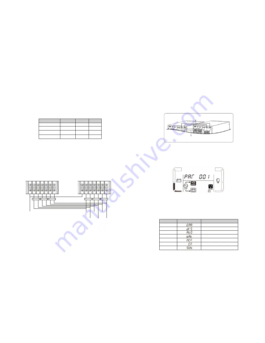
3-7. UPS parameter settings

Three parameters need to be configured in order to set up the UPS. Refer to the following diagram.

List of the 15 programs for parameter 1:

ENA
DIS
ATO
BAT

Enable
Disable
Auto
Battery

Abbreviation

Display content

Meaning

NCF
CF
SUB

Normal mode (not CVCF mode)
CVCF mode
Subtract

Communication port connection

Parallel cable connections

Summary of Contents for FDC-106K

Page 1: ...2 y e a r W a r r a n t y User Manual Uninterruptible Power Supply System FDC 106K FDC 110K...

Page 2: ...3 Initial setup Do not connect appliances or equipment that may overload the UPS system such as big motor type equipment to the UPS output sockets or terminal Place cables in such a way that no one c...

Page 3: ...he carrier or dealer where you purchased the unit Safety IEC EN 62040 1 EMI Conducted emission Radiated emission EMS ESD RS EFT SURGE CS Power frequency magnetic field Low frequency signals Warning Th...

Page 4: ...input and output wires and the input and output terminals are connected tightly Note 2 There are two output terminal configurations to meet customers diverse requirements for serial or parallel connec...

Page 5: ...with a technician to ensure that the load current will not exceed this limitation Note 2 When connecting to low voltage and high voltage at the same time as described in option 4 the L1 N1 and L2 N2...

Page 6: ...for calculating the capacity of the UPS as energy consumption increases during initial power on Description UPS status Bypass mode Battery mode Fault mode Warning Overload Others Fault All Buzzer stat...

Page 7: ...inverter has been turned off Note 2 After turning off the UPS please beware that the UPS is operating in Bypass mode and there is a risk of power loss for connected devices 2 In Bypass mode output vol...

Page 8: ...it will cause permanent damage to the equipment 5 Connect both parallel cables between each UPS the communications cable DB 25 and the load balancing cable as illustrated below Once the above connect...

Page 9: ...ing Parameter 2 Output frequency To set the output frequency choose any of the following three options in parameter 2 50 0Hz The output frequency is set to 50 0Hz 60 0Hz The output frequency is set to...

Page 10: ...0 of the nominal voltage Interface Setting 06 Voltage range for ECO mode Parameter 2 Sets low frequency point for ECO mode 50Hz system Ranges from 46 0Hz to 48 0Hz 60Hz system Ranges from 56 0Hz to 58...

Page 11: ...tery specifications Interface Setting 14 Charger voltage adjustment 15 Output voltage adjustment Parameter 2 You may choose Add or Sub to adjust the output voltage Parameter 3 The voltage ranges from...

Page 12: ...e switch is open Bypass is unstable Boot loader is missing Warning event Battery is not connected Over charge Low battery Overload Fan failure EPO enable Over temperature Charger failure Locked in byp...

Page 13: ...rning code blink on the LCD display and the alarm starts beeping once every second The and icons blink on the LCD display and the alarm starts beeping once every second The and icons blink on the LCD...

Page 14: ...Environment Operating temperature Storage temperature Relative humidity Operating altitude Audible noise Physical appearance Product Dimensions Product Weight Additional information Warranty 6000VA 6...

Page 15: ...www forzaups com...

Reviews: