Manual # 26-6090901-00 / Revision D
ViewMAX – High Performance Down Converter 35
other Folsom Research compatible devices to be controlled by one host computer system in a multi-dropped
environment. Each device on the RS-485 data bus must have a unique device ID to implement the poll/response
communication protocol.
RS-485 Connector Pinout/Interface Signal Definition
Interface Type:
Serial conforming to EIA RS-485 specifications
Mating Connector Type:
DB-9
male
Signal Levels:
+/-5V
Maximum Interface Cable Length:
4000 feet
RS-485 Rear Panel Connector Signal Definition
Pin
Signal
Direction
1 Receive
Data
RX+ Input
2
Transmit Data TX+
Output
3
Transmit Data TX-
Output
4 Receive
Data
RX- Input
5 Ground
6 N/C
7 N/C
8 N/C
9 N/C
Note: Direction is specified with respect to the ViewMAX unit
.
The RX+ data line should be connected to the host TX+ line.
The RX- data line should be connected to the host TX- line.
The TX+ data line should be connected to the host RX+ line.
The TX- data line should be connected to the host RX- line.
The recommended cable is low capacitance RS-485 cable with two twisted pairs, one pair for transmit and one for
receive. Shielding is not required.
Do not connect the Ground pin between systems that are not connected to the same AC branch line circuit to avoid
ground loops.
Devices should be connected to the RS-485 data bus in-line, that is, avoid designing an RS-485 bus as a trunk line
with branches to the devices. Instead, daisy chain the RS-485 bus from one device to the next.
A load resistor will be necessary at each end of the RS-485 data bus on the receive lines. If communication is poor
between the host and the remote devices (indicated by few or no responses to commands when the baud rate, parity,
data bits, and stop bits are all configured correctly), connect a 120 Ohm resistor across the RX- and RX+ terminals of
the last device on the bus. If communications improves but is not 100% reliable, lower the resistance value to 75
Ohms and try again. If the communications does not improve, it is likely that the cable length is too long for the type
of cable being used. A jumper is available on some ViewMAX models to enable a 120 Ohm load resistor. If a 2-pin
header connector, “E1” is located on the main board directly behind the serial port connectors, installing a jumper to
connect the two pins of E1 together will enable the 120 Ohm resistor. If E1 is located near J11 instead of near the
serial ports, then an external load resistor will be required.
RS-485 Port Configuration
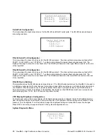
The RS-485 default setup is 38.4K baud, 8 data bits, 1 stop bit, and no parity, and device slave ID of 1. Each device
on the RS-485 bus must have a unique device address (1...32, inclusive). The baud rate and RS-485 slave ID may
be changed via the front panel or serial command.
RS-485 Command Format
An RS-485 command line string consists of the following components:

