background image


©2021 Flavor Burst Company                                                  Printed in September   


Printed in  

All Rights Reserved 


                               The United States of America
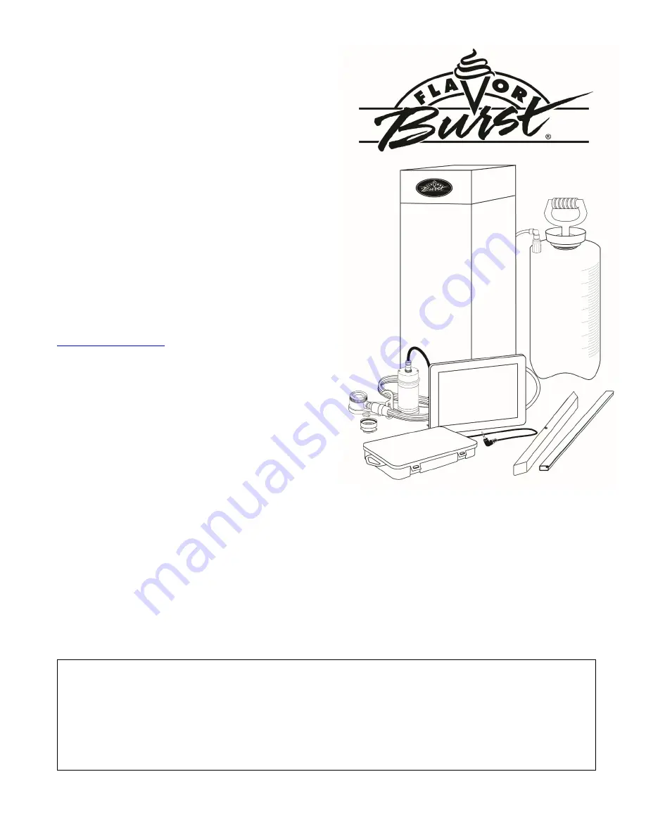
 

Flavor Burst

 ®


Frozen Beverage System 
Model CTP 80BEV 
 

Equipment, Maintenance and 
Operations Manual


Manufactured by 
 
Flavor Burst Company 
499 Commerce Drive 
Danville, IN  46122 
 
For general information and to locate a 
distributor near you, call or visit our website: 
Phone:  (317) 745-2952 
Toll Free Number: (800) 264-3528 
Fax:  (317) 745-2377 

www.flavorburst.com


For pricing, ordering and support, contact one 
of our qualified distributors. 


Warranty 


An installation and warranty form is provided with every CTP 80BEV system, located inside the CTP 
80BEV unit with this manual.  It is important that the operator carefully review the warranty and 
installation documents accompanying the unit before using this system.  Any questions or concerns 
regarding the warranty should be clarified upon delivery or installation.  For more information, contact 
your local authorized Flavor Burst


®

 distributor. 

Summary of Contents for CTP 80BEV

Page 1: ...ll Free Number 800 264 3528 Fax 317 745 2377 www flavorburst com For pricing ordering and support contact one of our qualified distributors Warranty An installation and warranty form is provided with...

Page 2: ...sembling the Blending Assembly 31 Sanitizing the Blending System 31 Replacing the Syrup Flavors 34 Scheduled Maintenance 38 Clean In Place CIP Procedure 38 CIP Phase 1 Prep 38 CIP Phase 2 Flush 40 CIP...

Page 3: ...e Blending System and Suspension Bracket 57 Mounting the Tube Cable Casing Assembly 59 Mounting the Plastic Casing Assembly 60 Connecting the Unit Syrup Line 61 Installing and Filling the Sanitizer Ta...

Page 4: ...use harmful interference to radio or television reception which can be determined by turning the equipment off and on the user is encouraged to try to correct the interference by one or more of the fo...

Page 5: ...l on the system Touch Panel Components of the CTP 80BEV system should be cleaned daily to ensure the highest standard of sanitation When your equipment is delivered or if it has been unused for more t...

Page 6: ...nce can be used by children aged from 8 years and above and persons with reduced physical sensory or mental capabilities or lack of experience and knowledge if they have been given supervision or inst...

Page 7: ...6 PAGE INTENTIONALLY LEFT BLANK...

Page 8: ...5800BEV SPARE PARTS KIT TOUCHSCREEN BEVERAGE 1 Houses extra spare parts and wear items 6 CAB 113 FLAVOR TRAY 8 Houses syrup bags 7 N A FLAVOR BURST FROZEN BEVERAGE CABINET ASSEMBLY 1 Houses syrup tray...

Page 9: ...8 General System Overview Figure 1...

Page 10: ...rays 14 CAB 144R RIGHT PANEL BRACKET 3 Holds tray support rails 15 CAB 144L LEFT PANEL BRACKET 3 Holds tray support rails 16 CAB 143 LATCH BRACKET 1 Provides latching tab for front panel latch 17 FAS...

Page 11: ...screw and holds rubber bumper in place 32 MIS 3074 SHORTY PLUG 1672 6 Covers screw hole in rubber bumper 33 FAS 2040 6 32 X 1 4 TAPPING SCREW 24 Secures tray support bracket to side panels 34 CAB 135L...

Page 12: ...connectors 4D INJ 116 LINE COUPLER NUT BLACK 1 ea Attaches flavor tubes to flavor manifold 4E SYR 901 6 9 TUBE ASSEMBLY TUBES 9 ea Brings syrup from pump to Blending Head 4F ROT 511 LINE COUPLER NUT 1...

Page 13: ...11B ADPT 104R CROWN ADAPTER WITOUT O RINGS 1 ea Attaches Blending Assembly to freezer door 11C RUB 632 BLENDING ADAPTER O RING 1 ea Creates tension to secure adapter to Blending Head 12 MIS 3196 STAI...

Page 14: ...13 PAGE INTENTIONALLY LEFT BLANK...

Page 15: ...14 Blending Assembly and Related Parts Figure 3...

Page 16: ...ER 1 ea Fastens bag fitment to bag connector 2B TUB 811 TUBE SILICONE 188X 375 PE FB80 1 ea Provides sealed cavity inside bag fitment 2C FIX 1048 FITTING X BARB FB80 1 ea Connects bag coupler assembly...

Page 17: ...16 Syrup Pump and Related Parts Figure 4...

Page 18: ...and pump lines 6 MIS 3028 S CONNECTOR FLUSH ASSEMBLY SHAKE 1 Connects with flavor line to flush with sanitizer solution 7 FIX 1023 3 16 X 3 16 BARB TUBE CONNECT 1 Splices together flush tubes 8 TUB 8...

Page 19: ...18 Sanitizer Pump and Related Parts Figure 5...

Page 20: ...hole 4 MIS 3026S TOUCH PANEL CABLE CASING 1 Conceals and protects the Touch Panel cable as well as attaches it to the freezer 5 ELE 525M MALE TO MALE 48 SWITCH EXTENSION 1 Connects Touch Panel to the...

Page 21: ...IS 3216 CLOSURE PLUG 5 8 INCH 2 Closes up extra opening in the base panel 22 ELE 434 POWER CABLE 1 Supplies the electronics board with power 23 ELE 927 RJ45 ETHERNET CABLE GLAND 1 Secures the Ethernet...

Page 22: ...21 PAGE INTENTIONALLY LEFT BLANK...

Page 23: ...22 Electronic Parts and Connections Figure 6...

Page 24: ...s adapter to Blending Head with tension 7 RUB 652 RSS SMALLER SYRUP PORT O RING 1 Provides sealed cavity inside syrup port 8 RUB 660 LARGER SYRUP PORT O RING 1 Provides sealed cavity inside syrup port...

Page 25: ...24 Spare Parts Kit Figure 7...

Page 26: ...25 PAGE INTENTIONALLY LEFT BLANK...

Page 27: ...This is typically performed at the close of the previous business day Sanitizing the Blending System 1 Prepare a small amount of sanitizer solution by mixing half a packet 1 oz of Stera Sheen Green La...

Page 28: ...ngs and the Gear Cartridge are wear items and will need to be replaced periodically Check for wear occasionally and always keep spares of these items on hand in the Spare Parts Kit 1 Place the Gear Ca...

Page 29: ...t the Drive Motor cable to the Motor 5 Ensure that the Blending Assembly is level horizontally and make any adjustments to the suspension bracket as needed using the adjustment hand knob 6 Insert the...

Page 30: ...d and adjusted if necessary 1 Ensure that the Sanitizer Tank has plenty of approved sanitizer solution that is no older than 28 days Refill if necessary 2 Ensure that desired flavors are installed and...

Page 31: ...the Blending System from the freezer during closing 1 With a container under the dispensing spout press the FLUSH SPOUT button on the Touch Panel to purge any remaining product from the spout NOTE IF...

Page 32: ...om the door spout 7 Remove any o rings and or gaskets from the inside and outside the adapter body Disassembling the Blending Assembly 1 Rotate the Drive Motor to unlock and remove the Drive Motor fro...

Page 33: ...warm detergent water then rinse thoroughly with warm water 108 F 42 C Use a small brush to ensure the syrup orifices are completely clear 5 When the Gear Box has soaked for at least 5 minutes brush an...

Page 34: ...anifold 12 Clean rinse and dry the surfaces of the Drive Motor and exposed surfaces of the cabinet using warm detergent water warm water 108 F 42 C and single service towels 13 The following do not ne...

Page 35: ...as previous flavors become empty However you may change flavors periodically as desired 1 Prepare detergent water by mixing several drops of Dawn dish soap with a gallon of warm water 108 F 42 C Prepa...

Page 36: ...le service towel 10 Select the flavor you wish to use then place the bag on the table with the fitment up and remove the dust cap 11 Lifting up with the bag fitment press the center pin of the bag fit...

Page 37: ...peat Steps 3 18 for any additional flavors that are being changed out 20 After the line in sanitized select Priming Functions in the Maintenance Menu 21 Select the flavor button of the line to be prim...

Page 38: ...37 PAGE INTENTIONALLY LEFT BLANK...

Page 39: ...s Flo San and Stera Sheen Green Label mixed according to the product manufacturer s instructions This Clean In Place procedure is detailed in four phases 1 Prep 2 Flush 3 Clean 4 Reassemble To ensure...

Page 40: ...e parts in warm detergent water 7 Place the end of the 9 Tube Assembly into a container to catch the expelled syrup and sanitizer solution during the rest of the Clean In Place procedure 8 Disconnect...

Page 41: ...ctions outlined on the Touch Panel screen to flush the syrup line 14 When the flushing process is complete disconnect the Pump Flush Adapter and repeat the process for the second line then the third a...

Page 42: ...18 Remove the rest of the parts from the sanitizer solution and place them on a sanitary tray to dry 19 Clean the exposed surfaces of the bag fitment and the syrup bag connector with warm detergent w...

Page 43: ...ully into the coupler base 25 Push the coupler nut into the coupler body and rotate the coupler body until motion stops to secure 26 Install the cap on the manifold 27 Perform the Assembling the Blend...

Page 44: ...ighten sufficiently NOTE NO PRESSURE IS NEEDED IN THE TANK DURING NORMAL OPERATIONS Priming the Syrup System Priming the syrups is necessary when first installing the flavors after the Clean In Place...

Page 45: ...er 108 F 42 C 2 Remove the worn o rings from the Blending Head A small tool may be used to remove the two o rings in the syrup line opening 3 Brush and clean all exposed surfaces of the Blending Head...

Page 46: ...towel 4 Clean the outside and underside of the cabinet using detergent water and single service towels 5 Carefully return the cabinet to its original place Inside of the Cabinet 1 If necessary disconn...

Page 47: ...ube Assembly if necessary according to instructions in Phase 4 of the Clean In Place procedure Touch Panel and Mounting Bracket NOTE DO NOT GET WATER NEAR THE CABLE CONNECTIONS OR SPEAKER HOLES ON THE...

Page 48: ...check valve and manifold 3 Place the 9 Tube Assembly line inside a container 4 Remove each syrup bag from its tray and store as directed on the label 5 Empty the Sanitizer Tank and return the tank to...

Page 49: ...ME BY PRESSING CANCEL 12 Repeat Steps 10 and 11 for the second line then the third and so on until all the lines have been cleared of sanitizer solution 13 When all lines have been emptied return the...

Page 50: ...49 PAGE INTENTIONALLY LEFT BLANK...

Page 51: ...EIT FOR CORRECT OPERATION NOTE INSTALL THE SYSTEM IN A LOCATION WHERE ITS USE AND MAINTENANCE IS RESTRICTED TO TRAINED PERSONNEL Installing the Color Touch Panel and Side Mounting Bracket The Touch Pa...

Page 52: ...BOTTOM OF THE TOUCH PANEL IS ABOVE THE BOTTOM OF THE FREEZER SPOUT 5 Remove the Color Touch Panel and Touch Panel plate from the rest of the bracket assembly Secure the freezer plate to the freezer u...

Page 53: ...our freezer depend on the freezer model as well as what product is being used shake vs slush etc If the installer has the correct integrated switches install these instead of the external switches inc...

Page 54: ...d configurations Determine which switch assembly configuration works best with your freezer When possible mount the switch directly onto the face of the freezer 3 Determine the approximate position wh...

Page 55: ...ATING PARTS ON THE FRONT OF THE FREEZER Installing the ELE 510 Draw Switch Internally on a Taylor 428 432 Freezer Flavor Burst highly recommends integrated switches be installed to power the CTP 80BEV...

Page 56: ...N THE DRAW HANDLE IS IN THE OPEN POSITION 5 Slide the switch cable jack through the center slot at the back of the panel 6 Replace the front panel 7 Connect one end of the switch extension to the ELE...

Page 57: ...emove the manifold cap and set it on a sanitary tray Spray the syrup line manifold opening with approved sanitizer solution and allow it to sanitize for at least 5 minutes 5 Place the 9 Tube Assembly...

Page 58: ...The suspension bracket helps stabilize the Blending Assembly on the freezer When properly installed on the freezer the bracket should hold the Blending Assembly level horizontally with the Blending He...

Page 59: ...e Blending Assembly so that it is not in the way of the second barrel 1 Determine how the Blending Assembly will be positioned on the freezer When possible follow the recommended position outlined abo...

Page 60: ...t it hangs straight down from the door nut 6 Use the thumb screw to adjust the bracket vertically so that it supports the Blending Assembly in a level position 7 Tighten the thumb nut and screws to se...

Page 61: ...side the cable exits the assembly 1 Prepare detergent water by mixing several drops of Dawn dish soap with a gallon of warm water 108 F 42 C 2 The Casing Assembly contains very power magnets to attach...

Page 62: ...fic areas of the Flavor Burst system such as the Blending Head and syrup lines during certain functions Therefore check the tank levels on a daily basis For proper sanitation use only FRESH sanitizer...

Page 63: ...xpose the lead line coupler 2 Remove the 9 hole gasket from the end of the 9 Tube Assembly line Spray the end of the 9 Tube Assembly the gasket and the end of the lead with sanitizer solution Allow th...

Page 64: ...ernet cable to the ethernet port in the plastic gland Screw the plastic cover over the connection and secure the ethernet gland assembly with the nut 4 Connect the power cord to the port on the back p...

Page 65: ...avor you wish to use then place the bag on the table with the fitment up and remove the dust cap 4 Lifting up with the bag fitment press the center pin of the bag fitment valve and gently press on the...

Page 66: ...EDULED MAINTENANCE section The Clean In Place procedure MUST be done during the initial setup of the CTP 80BEV to ensure all the parts and syrup lines are sanitized and ready for use 11 After the Clea...

Page 67: ...eezer The CTP 80BEV system will also dispense plain product if no flavors are selected on the Touch Panel NOTE IN OUR CONTINUAL EFFORT TO IMPROVE OUR PRODUCTS PROGRAM UPGRADES MAY BE AVAILABLE FOR THE...

Page 68: ...CTIONS STILL APPLY 1 Select the product type from the product selection screen If the screen already displays flavor choices proceed to Step 5 2 The next screen may show options to select a container...

Page 69: ...handle down to dispense product If you have the timed servings enabled draw the serving until the system sounds a beep and the screen notifies you to stop drawing product Return the handle to the clo...

Page 70: ...red product at the top of your serving NOTE ADJUST THE WHITE CAP TIME IN THE ENABLE OR DISABLE SERVING OPTIONS SECTION OF THE MAINTENANCE MENU NOTE THE WHITE CAP OPTION IS ONLY AVAILABLE WHEN TIMED SE...

Page 71: ...rify the syrup pump is malfunctioning Contact your local distributor for help 13 On occasion it may be desirable to sanitize the Blending Head between servings Simply hold a container under the dispen...

Page 72: ...71 PAGE INTENTIONALLY LEFT BLANK...

Page 73: ...r and O Rings 9 Tube Assembly Opening DAILY CLOSING PROCEDURES page 30 Blending Head Gear Cartridge Gear Box Spout Adapter and O Rings 9 Tube Assembly Opening Drive Motor Touch Panel Exposed Surfaces...

Page 74: ...Spare Parts Kit should contain replacements for these wear items Be sure to keep replacements in stock inside the Spare Parts Kit for easy access PARTS REPLACEMENT SCHEDULE Part No Part Description E...

Page 75: ...stallation requirements This includes adapter kits adapters brackets and switches for various freezer models and manufacturers Please contact your local distributor or visit us online at www flavorbur...

Page 76: ...nel inside the cabinet Complete for quick reference when this information is requested 1 Model Number CTP 80BEV _____________________________ 2 Serial Number ____________________________________ 3 Vol...

Reviews: