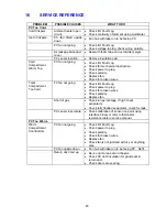
321037
75
13.4 Compressor
Replacement
COMPRESSOR With No Oil Cooler
1. Disconnect the refrigerator from the power supply. Empty the freezer.
2. Recover refrigerant from the system by fitting a line tap valve to the process pipe on the
compressor and connecting to a recovery unit.
3. Remove the relay cover from the compressor and remove the connector from the compressor
electrical pins.
4. Unbraze the compressor suction, discharge and defrost water tray heater pipes. Cut if a
blockage is suspected.
5. Remove the water tray by removing the two screws.
6. Remove the retaining clips from the compressor mounting pins and lift the compressor clear of
the unit compartment. Seal the compressor lines.
7. Fit the new compressor to the mounting pins and refit the retaining clips.
8. Refit the piping such as the suction, discharge and water evaporator heater.
9. Fit a new charging tail/process pipe.
10 Replace the filter dryer. The filter is to be removed by cutting from the system, do not heat the
filter to unbraze.
11. Purge the system with nitrogen. (This is a must before any brazing takes place.)
12. Braze all the pipes.
13. Pressurise the system and test for leaks.
COMPRESSOR PIPING LAYOUT
Diagram 13.4
1. Service tube (process pipe).
2. Suction
line.
3. Discharge line into condenser.
4. Condenser to mullion.
5. Mullion to filter.
6. Capillary
tube.
7. Filter
dryer.
8. Filter process pipe.
1
4
5
8
2
3
7
6
Summary of Contents for RF175W
Page 1: ...321037 Service Manual Active Smart Refrigerator Freezer Models RF195A RF175W...
Page 19: ...321037 19 5 4 5 Condenser Mullion Layout Diagram 5 4 5...
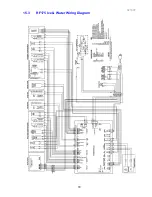
Page 77: ...321037 77 15 WIRING DIAGRAM 15 1 RF175 Wiring Diagram...
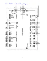
Page 78: ...321037 78 15 2 RF175 Control Module Wiring Diagram...
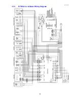
Page 79: ...321037 79 15 3 RF175 Ice Water Wiring Diagram...
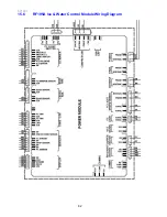
Page 80: ...321037 80 15 4 RF175 Ice Water Control Module Wiring Diagram...
Page 81: ...321037 81 15 5 RF195A Ice Water Wiring Diagram...
Page 82: ...321037 82 15 6 RF195A Ice Water Control Module Wiring Diagram...

